IMPORTANT MANUAL Do Not Throw Away OWNER'S MANUAL MODEL NUMBER: PP208E24 SNOW THROWER WARNING: Read the Owner's Manual and follow all Warnings and Safety Instructions. Failure to do so can result in serious injury. Always Wear Eye Protection During Operation 428496 Rev 1 07.10.09 TH Printed in the U.S.A.
IMPORTANT Safe Operation Practices for Walk-Behind Snow Throwers This snow thrower is capable of amputating hands and feet and throwing objects. Failure to observe the following safety instructions could result in serious injury. WARNING: Snow throwers have exposed rotating parts, which can cause severe injury from contact, or from material thrown from the discharge chute. Keep the area of operation clear of all persons, small children and pets at all times including startup.
6. When cleaning, repairing or inspecting the snow thrower, stop the engine and make certain the collector/impeller and all moving parts have stopped. Disconnect the spark plug wire and keep the wire away from the plug to prevent someone from accidentally starting the engine. 7. Do not run the engine indoors, except when starting the engine and for transporting the snow thrower in or out of the building. Open the outside doors; exhaust fumes are dangerous. 8.
PARTS PACKED SEPARATELY IN CARTON (1) AUGER CONTROL ROD (1) MULTIWRENCH (180684) (1) DISCHARGE CHUTE (3) RETAINER SPRINGS (169675) (1) POWER CORD (198563) (2) FLAT WASHERS ROTATOR HEAD MOUNTING (2) CARRIAGE BOLTS 3/8-16 x 2.25 (1) WASHER 3/8 (19131316) (1) LOCKNUT 3/8 (73800600) (2) SAFTEY IGNITION KEY (422663) (2) HANDLE KNOBS EXTRA SHEAR BOLTS AND NUTS (2) SHEAR BOLTS 1/4-20 x 1-3/4 (192090) (2) LOCKNUTS 1/4-20 (73800400) ASSEMBLY / PRE-OPERATION 2.
ASSEMBLY / PRE-OPERATION NOTE: The multi-wrench may be used for assembly of the chute rotator head to snow thrower and making adjustments to the skid plates. INSTALL TRACTION DRIVE CONTROL ROD (See Figs. 3 and 4) The traction drive control rod is installed on the snow thrower. 1. Remove plastic tie securing rod to lower handle. 2. With top end of rod positioned under left side of control panel, push rod down and insert top end of rod into hole in drive control bracket. Secure with retainer spring.
ASSEMBLY / PRE-OPERATION INSTALL DISCHARGE CHUTE / CHUTE ROTATER HEAD (See Fig. 7) NOTE: The multi-wrench provided in your parts bag may be used to install the chute rotater head. 1. Place discharge chute assembly on top of chute base with discharge opening toward front of snow thrower. 2. Position chute rotater head over chute bracket. If necessary, rotate chute assembly to align square and pin on underside of chute rotater head with holes in chute bracket. 3.
OPERATION KNOW YOUR SNOW THROWER READ THIS OWNER'S MANUAL AND ALL SAFETY RULES BEFORE OPERATING YOUR SNOW THROWER. Compare the illustrations with your snow thrower to familiarize yourself with the location of various controls and adjustments. Save this manual for future reference. These symbols may appear on your snow thrower or in literature supplied with the product. Learn and understand their meaning.
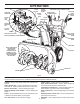
OPERATION MUFFLER ELECTRIC START BUTTON GASOLINE FILLER CAP AUGER CONTROL LEVER POWER CORD PLUG CHOKE CONTROL DISCHARGE CHUTE CONTROL LEVER DRIVE SPEED CONTROL LEVER TRACTION DRIVE CONTROL LEVER CHUTE DEFLECTOR SAFETY IGNITION KEY ON / OFF SWITCH DISCHARGE CHUTE PRIMER CHUTE DEFLECTOR KNOB FUEL SHUT-OFF VALVE RECOIL (AUXILIARY) STARTER HANDLE HANDLE KNOB CLEAN-OUT TOOL MUFFLER NOTE: ITEMS ABOVE ARE SHOWN IN THEIR TYPICAL LOCATION ON THE ENGINE.
OPERATION The operation of any snow thrower can result in foreign objects thrown into the eyes, which can result in severe eye damage. Always wear safety glasses or eye shields while operating your snow thrower or performing any adjustments or repairs. We recommend standard safety glasses or a wide vision safety mask worn over spectacles. TO CONTROL SNOW DISCHARGE (See Figs.
OPERATION TO THROW SNOW (See Fig. 13) The auger rotation is controlled by the auger control lever located on the right side handle. • Squeeze auger control lever to handle to engage the auger and throw snow. • Release the auger control lever to stop throwing snow. TO MOVE FORWARD AND BACKWARD (See Fig. 15) SELF-PROPELLING, forward and reverse movement of the snow thrower, is controlled by the traction drive control lever located on the left side handle.
OPERATION TO ADJUST SKID PLATES (See Fig. 16) NOTE: The wrench provided in your parts bag may be used to adjust the skid plates. Skid plates are located on each side of the auger housing and adjust the clearance between the scraper bar and the ground surface. Adjust skid plates evenly to proper height for current surface conditions.
OPERATION TO START ENGINE • Be sure fuel shut-off valve is in the “OPEN” position. Your snow thrower engine is equipped with both a 120 Volt A.C. electric starter and a recoil starter. The electric starter is equipped with a three-wire power cord and plug and is designed to operate on 120 Volt A.C. household current. • Be sure your house is a 120 Volt A.C. three-wire grounded system. If you are uncertain, consult a licensed electrician. 6.
MAINTENANCE GENERAL RECOMMENDATIONS LUBRICATION CHART The warranty on this snow thrower does not cover items that have been subjected to operator abuse or negligence. To receive full value from the warranty, operator must maintain snow thrower as instructed in this manual. Some adjustments will need to be made periodically to properly maintain your snow thrower. At least once a season, check to see if you should make any of the adjustments described in the Service and Adjustments section of this manual.
MAINTENANCE V-BELTS Check V-belts for deterioration and wear after every 50 hours of operation and replace if necessary. The belts are not adjustable. Replace belts if they begin to slip from wear. (See “TO REMOVE BELT COVER” in the Service and Adjustments section of this manual). The V-belts on your snow thrower are of special construction and should be replaced by original equipment manufacturer (OEM) belts available from your nearest dealer.
SERVICE AND ADJUSTMENTS 3. Make sure the augers and all moving parts have completely stopped. To replace the capscrew/shear bolts: 1. Disengage all controls and move throttle control to STOP position. Wait for all moving parts to stop. 2. Remove safety ignition key and disconnect spark plug wire from spark plug. Place wire where it cannot come in contact with spark plug. 3. Align holes in impeller hub with holes in impeller shaft and install two (2) new 1/4-20 x 1-5/8" capscrew/shear bolts.
SERVICE AND ADJUSTMENTS TO REPLACE BELTS (See Fig. 20) The auger and traction drive belts are not adjustable. If the belts are damaged or begin to slip from wear, they should be replaced. It is recommended that the belt(s) be replaced by a service center/department. NOTE: It is recommended that both the auger and traction drive belt be replaced at the same time.
SERVICE AND ADJUSTMENTS TO ADJUST CABLE TENSION (See Fig. 22) Adjust cable tension by turning the adjuster turn buckle, located on the right hand cable. Grasp the long section tightly and turn the short section to lengthen the adjuster. Adjust until cable is snug. TO REMOVE WHEELS (See Fig. 21) • Remove the klik pin and remove wheel from axle. IMPORTANT: When installing wheel, be sure to use the innermost hole in axle and the wheel hub hole.
STORAGE Immediately prepare your snow thrower for storage at the end of the season or if the unit will not be used for 30 days or more. • Empty the fuel tank by starting the engine and letting it run until the fuel lines and carburetor are empty. • Never use engine or carburetor cleaner products in the fuel tank or permanent damage may occur. • Use fresh fuel next season. NOTE: Fuel stabilizer is an acceptable alternative in minimizing the formation of fuel gum deposits during storage.
TROUBLESHOOTING See appropriate section in manual unless directed to an authorized service center/department. PROBLEM Does not start CAUSE 1. Fuel shut-off valve (if so equipped) in OFF position. 2. Safety ignition key is not inserted. 3. Out of fuel. 4. Throttle in STOP position 5. Choke in OFF position. 6. Primer not depressed. 7. Engine is flooded. 8. Spark plug wire is disconnected. 9. Bad spark plug. 10. Stale fuel. 11. Water in fuel. CORRECTION 1. Turn fuel shut-off valve to OPEN position. 2.
REPAIR PARTS SNOW THROWER - - MODEL NUMBER PP208E24 (96198002600) AUGER HOUSING / IMPELLER ASSEMBLY 5 11 11 6 7 15 14 16 12 13 8 11 4 12 17 3 10 11 1 9 2 33 32 34 30 31 26 31 29 28 36 20 27 23 22 21 25 35 24 23 22 21 18 2 (EXPLODED) 19 01.07.004-C NOTE: All component dimensions given in U.S. inches. 1 inch = 25.4 mm IMPORTANT: Use only Original Equipment Manufacturer (O.E.M.) replacement parts. Failure to do so could be hazardous, damage your snow thrower and void your warranty.
REPAIR PARTS SNOW THROWER - - MODEL NUMBER PP208E24 (96198002600) AUGER HOUSING / IMPELLER ASSEMBLY KEY NO. PART NO.
REPAIR PARTS SNOW THROWER - - MODEL NUMBER PP208E24 (96198002600) AUGER HOUSING / IMPELLER ASSEMBLY 1 KEY NO. PART NO. DESCRIPTION 1 2 3 4 404928X428 404931X479 72270505 155377 AUGER HOUSING SCRAPPER BAR CARRIAGE BOLT 5/16−18 X .625 NUT 5/16−18 KEY NO. PART NO. DESCRIPTION 1 2 420493X479 420494X479 AUGER ASSEMBLY LH 24 AUGER ASSEMBLY RH 24 3 (5x) 4 (5x) 2 01.07.001-A 2 1 01.07.017-A NOTE: All component dimensions given in U.S. inches. 1 inch = 25.
REPAIR PARTS SNOW THROWER - - MODEL NUMBER PP208E24 (96198002600) AUGER HOUSING / IMPELLER ASSEMBLY 2 3 1 1 2 KEY NO. PART NO. DESCRIPTION 1 2 3 420478 411939 179582 AUGER BEARING BEARING PLUG SCREW 5/16−18 X 1.00 3 01.07.024-B 3 4 2 4 3 01.11.001-A 1 KEY NO. PART NO. DESCRIPTION 1 2 3 4 174762X479 178777X479 72270506 751153 SKID PLATE LH SKID PLATE RH CARRIAGE BOLT 5/16−18 X .75 NUT 5/16−18 NOTE: All component dimensions given in U.S. inches. 1 inch = 25.
REPAIR PARTS SNOW THROWER - - MODEL NUMBER PP208E24 (96198002600) CONTROL PANEL / CHUTE 2 11 10 5 8 3 6 9 11 4 6 11 7 1 01.09.001-A KEY NO. PART NO. DESCRIPTION 1 2 3 4 5 6 7 8 9 10 11 404770X428 178633X428 420325 179096X479 189713X428 128415 185600 72270505 191730 155415 179246 CHUTE WELDMENT DEFLECTOR WELDMENT DEFLECTOR SEAL STRAP KNOB BLACK POP RIVET SHOULDER BOLT 1/4−20 X .704 CARRIAGE BOLT 5/16−18 X .625 NUT 1/4−20 WASHER PLASTIC WASHER NOTE: All component dimensions given in U.S. inches.
REPAIR PARTS SNOW THROWER - - MODEL NUMBER PP208E24 (96198002600) CONTROL PANEL / CHUTE 2 2 1 *3 *7 *6 *4 KEY NO. PART NO. DESCRIPTION 1 2 *3 *4 *5 *6 *7 428272 17501010 420678 405932 420675 428273 428310 LEVER/CABLE ROTATOR ASSEMBLY SCREW 10-24 X .625 ROTATOR HEAD ROTATOR PIVOT BRACKET PULLEY PIVOT CABLE ASSEMBLY ADJUSTABLE CABLE ASSEMBLY HEAT SHIELD 01.09.010-A NOTES: 1. ITEMS INDICATED WITH AN * ARE LISTED AS REFERENCE FOR SERVICE PARTS ONLY. NOTE: All component dimensions given in U.S.
REPAIR PARTS SNOW THROWER - - MODEL NUMBER PP208E24 (96198002600) HANDLES 5 1 6 8 7 2 5 3 8 6 9 7 8 4 9 KEY NO. 1 2 3 4 5 6 7 8 9 PART NO. 419800X479 419801X479 196944 196943 199513 74780512 74780524 751153 155415 DESCRIPTION PLOW HANDLE LH PLOW HANDLE RH PANEL BRACKET LH PANEL BRACKET RH HANDLE GRIP SCREW 5/16−18 X .750 SCREW 5/16−18 X 1.50 NUT 5/16−18 WASHER KEY NO. PART NO. DESCRIPTION 1 2 3 4 419797X479 418313X479 428867 17000616 LOWER TUBE PIVOT SUPPORT BOLT 5/16-18 X .
REPAIR PARTS SNOW THROWER - - MODEL NUMBER PP208E24 (96198002600) HANDLES 10 2 11 8 4 7 9 9 5 6 7 1 12 3 13 8 13 14 14 01.08.002-F 12 KEY NO. 1 2 3 4 5 6 7 8 9 10 11 12 13 14 PART NO. 412683X479 424517X179 424516X479 426917X008 426918X008 412677 421613 169675 17060410 414280 414281 178899 19131316 72120618 DESCRIPTION CONTROL PANEL CONTROL LEVER LH CONTROL LEVER RH TRACTION ROD ARM IMPELLER ROD ARM INTERLOCK ROD SPACER RETAINER SCREW 1/4-20 X .
REPAIR PARTS SNOW THROWER - - MODEL NUMBER PP208E24 (96198002600) HANDLES 2 10 10 3 1 8 9 KEY NO. PART NO. DESCRIPTION 1 2 3 4 5 6 7 8 9 10 180480 405740 180445 187716 180447 178669 180926 72270505 155377 169675 IMPELLER ROD TRACTION ROD SHIFTER ROD TOP SHIFTER ROD BOTTOM SPRING SLEEVE IMPELLER SPRING TRACTION SPRING CARRIAGE BOLT 5/16-18 X .75 NUT 5/16-18 RETAINER 4 5 7 10 5 6 01.12.001-E NOTE: All component dimensions given in U.S. inches. 1 inch = 25.
REPAIR PARTS SNOW THROWER - - MODEL NUMBER PP208E24 (96198002600) HANDLES 3 1 2 KEY NO. 1 2 3 PART NO. 183352 184471 175262 DESCRIPTION CONSOLE PANEL SCREW 10−24 X .625 SCREW 10−24 X 1.25 KEY NO. PART NO. DESCRIPTION 1 2 3 4 5 6 412675X004 414572 178831 169675 17060410 421252X004 INTERLOCK SPRING INTERLOCK CAM TORSION SPRING RETAINER SCREW 1/4−20 X .625 INTERLOCK STOP 3 2 01.10.001-B 4 3 2 5 1 6 01.08.007-B NOTE: All component dimensions given in U.S. inches. 1 inch = 25.
REPAIR PARTS SNOW THROWER - - MODEL NUMBER PP208E24 (96198002600) DRIVE ITEM 42 EXPLODED 46 45 48 2 47 49 16 1 12 11 9 9 8 7 6 9 11 18 14 22 20 24 19 53 11 52 15 53 13 10 50 17 15 4 34 53 23 21 24 5 33 23 53 3 29 30 31 35 27 24 33 32 28 26 26 38 53 36 4 23 51 37 25 53 42 43 39 44 24 41 40 39 01.02.012-A NOTE: All component dimensions given in U.S. inches. 1 inch = 25.4 mm IMPORTANT: Use only Original Equipment Manufacturer (O.E.M.) replacement parts.
REPAIR PARTS SNOW THROWER - - MODEL NUMBER PP208E24 (96198002600) DRIVE KEY NO. PART NO. DESCRIPTION 1 2 3 4 5 6 7 8 9 10 11 12 13 14 15 16 17 18 19 20 21 22 23 24 25 26 27 198875 17501010 402685X428 17490508 57079 405485 198580 403097X004 402881 403096X004 191730 402856X004 416717X004 187101 700279 406109 402568 169675 401732 402310 12000036 402878 751153 408981 73930500 198176X479 179831 SPEED SELECTOR ASSEMBLY SCREW 10-24 X .625 END PLATE SCREW 5/16-18 X .
REPAIR PARTS SNOW THROWER - - MODEL NUMBER PP208E24 (96198002600) DRIVE 5 6 1b 7 4 3 1b 1a 6 2 3 5 4 01.03.005-B KEY NO. PART NO. DESCRIPTION 1 1a 1b 2 3 4 5 6 7 188226 179352 9465M 402691 174697 179830 17490508 155443 189282 (assy of 1a,1b) AXLE ASSEMBLY AXLE SHAFT ROLL PIN 3/16 SPROCKET THRUST WASHER BEARING BOLT 5/16−18 X .500 CLIK PIN SQUARE KEY NOTE: All component dimensions given in U.S. inches. 1 inch = 25.4 mm IMPORTANT: Use only Original Equipment Manufacturer (O.E.M.
REPAIR PARTS SNOW THROWER - - MODEL NUMBER PP208E24 (96198002600) CHASSIS / ENGINE / PULLEYS 2 3 2 3 1 01.00.034-A KEY NO. PART NO. DESCRIPTION -1 2 3 428169 418694X428 150406 428867 COMPLETE LCT ENGINE FRAME BOLT 3/8-16 SCREW 5/16-18 X .750 KEY NO. PART NO. DESCRIPTION 1 423184X428 ENGINE MOUNT PLATE KEY NO. PART NO. DESCRIPTION 1 2 409161 17490408 COVER ASSEMBLY SCREW 1/4-20 X .50 1 01.01.006-A 1 2 2 01.21.013-A NOTE: All component dimensions given in U.S. inches. 1 inch = 25.
REPAIR PARTS SNOW THROWER - - MODEL NUMBER PP208E24 (96198002600) CHASSIS / ENGINE / PULLEYS 24 23 25 14 14 22 13 22 21 20 19 21 18 11 17 12 14 16 15 6 4 8 5 3 7 1 10 2 9 01.21.001-A KEY NO. PART NO. DESCRIPTION 1 2 3 4 5 6 7 8 9 10 11 12 13 408007 419744 419925X479 193397X479 180523 74780524 426589 175330 85179 428867 187786 180522 74780520 IMPELLER BELT TRACTION BELT IDLER ARM IDLER BRACKET IDLER PULLEY SCREW 5/16-18 X 1.
REPAIR PARTS SNOW THROWER - - MODEL NUMBER PP208E24 (96198002600) WHEELS 1 KEY NO. PART NO. DESCRIPTION 1 2 187831X421 187866X421 WHEEL ASSEMBLY LH WHEEL ASSEMBLY RH 2 01.06.001-A NOTE: All component dimensions given in U.S. inches. 1 inch = 25.4 mm IMPORTANT: Use only Original Equipment Manufacturer (O.E.M.) replacement parts. Failure to do so could be hazardous, damage your snow thrower and void your warranty.
REPAIR PARTS SNOW THROWER - - MODEL NUMBER PP208E24 (96198002600) BAG OF PARTS 3 4 2 5 7 1 KEY NO. PART NO. DESCRIPTION 1 2 3 4 5 6 7 198563 169675 180684X008 73800600 19131316 192090 73800400 POWER CORD RETAINER PIN WRENCH LOCKNUT 3/8−16 WASHER 3/8 SHEAR BOLT 1/4−20 X 1−3/4 LOCKNUT 1/4−20 KEY NO. 1 PART NO. 422663 DESCRIPTION SAFETY IGNITION KEY 6 01.14.004-B 1 01.14.009-A 1 3 2 4 1 4 2 2.56 01.14.012-A KEY NO. 1 2 3 4 PART NO.
REPAIR PARTS SNOW THROWER - - MODEL NUMBER PP208E24 (96198002600) DECALS 1 4 7 9 6 1 3 11 KEY NO. PART NO. DESCRIPTION 1 3 4 6 7 9 11 181037 181035 181042 181033 415390 415475 415391 DECAL, DANGER DECAL, DANGER, DEFLECTOR DECAL, DANGER DECAL, INSTRUCTION DECAL, AUGER LEVER RT DECAL, SPEED CONTROL DECAL, TRACT/CLUTCH LEVER NOTE: All component dimensions given in U.S. inches. 1 inch = 25.4 mm IMPORTANT: Use only Original Equipment Manufacturer (O.E.M.) replacement parts.
SERVICE NOTES 38
SERVICE NOTES 39
LIMITED WARRANTY The Manufacturer warrants to the original consumer purchaser that this product as manufactured is free from defects in materials and workmanship. For a period of two (2) years from date of purchase by the original consumer purchaser, we will repair or replace, at our option, without charge for parts or labor incurred in replacing parts, any part which we find to be defective due to materials or workmanship. This Warranty is subject to the following limitations and exclusions. 1.