MODEL NO. CO24H48STA 24.0 HP 48 INCH LAWN TRACTOR For Parts and Service, contact our authorized distributor: call 1-800-849-1297 For Technical Assistance: call 1-800-829-5886 191697 03.01.04 TR PRINTED IN U.S.A.
TABLE OF CONTENTS Warranty ................................................ 2 Safety Rules .......................................... 3 Product Specifications ........................... 6 Assembly/Pre-Operation ....................... 8 Operation............................................. 13 Maintenance ....................................... 20 Maintenance Schedule ........................ 20 Service and Adjustments..................... 24 Storage ................................................
SAFETY RULES IMPORTANT: This cutting machine is capable of amputating hands and feet and throwing objects. Failure to observe the following safety instructions could result in serious injury or death. • Slow down before turning. WARNING: In order to prevent ac• Never leave a running machine unatcidental starting when setting up, transtended. Always turn off blades, set porting, adjusting or making repairs, parking brake, stop engine, and remove always disconnect spark plug wire and keys before dismounting.
SAFETY RULES • Follow the manufacturer’s recommendations for wheel weights or counterweights to improve stability. • Use extra care with grass catchers or other attachments. These can change the stability of the machine. • Keep all movement on the slopes slow and gradual. Do not make sudden changes in speed or direction. • Avoid starting or stopping on a slope. If tires lose traction, disengage the blades and proceed slowly straight down the slope.
SAFETY RULES • Remove obstacles such as rocks, tree limbs, etc. • Watch for holes, ruts, or bumps. Uneven terrain could overturn the machine. Tall grass can hide obstacles. • Use slow speed. Choose a low gear so that you will not have to stop or shift while on the slope. • Avoid starting or stopping on a slope. If tires lose traction, disengage the blades and proceed slowly straight down the slope. • If machine stops while going uphill, disengage blades, shift into reverse and back down slowly.
PRODUCT SPECIFICATIONS Gasoline Capacity and Type: Oil Type (API-SF-SJ): Oil Capacity: Spark Plug: (GapP: .040") Ground Speed (MPH): Tire Pressure: Charging System: Battery: Blade Bolt Torque: CUSTOMER RESPONSIBILITIES • Read and observe the safety rules. • Follow a regular schedule in maintaining, caring for and using your tractor. • Follow the instructions under “Maintenance” and “Storage” sections of this owner’s manual.
UNASSEMBLED PARTS Steering Wheel Steering Extension Shaft Steering Sleeve Steering Wheel Adapter Steering Wheel Insert (1) Large Flat Washer (1) Locknut 1/2-20 Nose Roller Gauge Wheels (4) Adjusting Bar Rod (4) Retainer Springs (double loop) (2) Locknuts 5/16-18 Nose Roller Brackets (2) Hex Bolts 5/16-18 x 1 (4) Locknut 3/8-16 (4) Washers 3/8 x 3/4 x 14 Ga.
ASSEMBLY/PRE-OPERATION Your new tractor has been assembled at the factory with the exception of those parts left unassembled for shipping purposes. To ensure safe and proper operation of your tractor all parts and hardware you assemble must be tightened securely. Use the correct tools as necessary to insure proper tightness. Review the video cassette before you begin. TOOLS REQUIRED FOR ASSEMBLY Steering Wheel Insert A socket wrench set will make assembly easier.
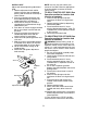
INSTALL SEAT Adjust seat before tightening adjustment knob. 1. Remove adjustment knob and flat washer securing seat to cardboard packing and set aside for assembly of seat to tractor. 2. Pivot seat upward and remove from the cardboard packing. Remove the cardboard packing and discard. 3. Place seat on seat pan so head of shoulder bolt is positioned over large slotted hole in pan. 4. Push down on seat to engage shoulder bolt in slot and pull seat towards rear of tractor. 5.
TO ATTACH NOSE ROLLER ASSEMBLE GAUGE WHEELS TO MOWER DECK 1. Assemble brackets "A" and "B" to the inside of mower mounting brackets as shown. Tighten securely. NOTE: Be sure bracket tabs are positioned in tab holes in mower brackets. 2. Position nose roller between brackets and install rod and retainer spring. Lock Nut The gauge wheels are designed to keep the mower deck in proper position when operating mower. Be sure they are properly adjusted to ensure optimum mower performance. 1.
9. Position front plate assembly between front mower brackets. Raise deck and plate assembly to align holes and insert flanged pins. Secure pins with double loop retainer springs between the plate assembly and mower brackets. NOTE: To assist in locating hole in flanged pin, the hole in pin is inline with notch on head of pin. If necessary, move mower side-to-side to give space between plate and mower brackets. IMPORTANT: Check belt for proper routing in all mower pulley grooves. 10.
✔CHECKLIST CHECK TIRE PRESSURE Before you operate your new tractor, we wish to assure that you receive the best performance and satisfaction from this quality product. Please review the following checklist: ✓ All assembly instructions have been completed. ✓ No remaining loose parts in carton. ✓ Battery is properly prepared and charged. (Minimum 1 hour at 6 amps). ✓ Seat is adjusted comfortably and tightened securely. ✓ All tires are properly inflated.
OPERATION These symbols may appear on your tractor or in literature supplied with the product. Learn and understand their meaning.
KNOW YOUR TRACTOR READ THIS OWNER'S MANUAL AND SAFETY RULES BEFORE OPERATING YOUR TRACTOR Compare the illustrations with your tractor to familiarize yourself with the locations of various controls and adjustments. Save this manual for future reference.
The operation of any tractor can result in foreign objects thrown into the eyes, which can result in severe eye damage. Always wear safety glasses or eye shields while operating your tractor or performing any adjustments or repairs. We recommend standard safety glasses or a wide vision safety mask worn over spectacles. 00155 • Never use choke to stop engine. IMPORTANT: Leaving the ignition switch in any position other than "STOP" will cause the battery to discharge and go dead.
• The average lawn should be cut to approximately 2-1/2 inches during the cool season and to over 3 inches during hot months. For healthier and better looking lawns, mow often and after moderate growth. • For best cutting performance, grass over 6 inches in height should be mowed twice. Make the first cut relatively high; the second to desired height.
BEFORE STARTING THE ENGINE • To restart movement, slowly release parking brake and clutch/brake pedal. • Slowly move motion control lever to slowest setting. • Make all turns slowly. CHECK ENGINE OIL LEVEL The engine in your tractor has been shipped, from the factory, already filled with summer weight oil. 1. Check engine oil with tractor on level ground. 2. Remove oil fill cap/dipstick and wipe clean, reinsert the dipstick and screw cap tight, wait for a few seconds, remove and read oil level.
AUTOMATIC TRANSMISSION WARM UP Before driving the unit in cold weather, the transmission should be warmed up as follows: 1. Be sure the tractor is on level ground. 2. Place the motion control lever in neutral. Release the parking brake and let the clutch/brake slowly return to operating position. 3. Allow one minute for transmission to warm up. This can be done during the engine warm up period.
NOTE: During this step there will be no movement of drive wheels. The air is being removed from hydraulic drive system. 5. Move motion control lever to neutral (N) position. Shutoff engine and set parking brake. 6. Engage transmission by placing freewheel control in engaged position (See “TO TRANSPORT” in this section of manual). 7. Sitting in the tractor seat, start engine. After the engine is running, move throttle control to half (1/2) speed.
MAINTENANCE MAINTENANCE SCHEDULE FILL IN DATES AS YOU COMPLETE REGULAR SERVICE E E S S RS AG US RS UR OUR OU SON OR U O H A ST HO 25 H 50 H 100 SE RE EE Y 8 R RY ERY ERY ERY FO OR E E F BE SERVICE EV EV EV EV EV BE H AC DATES Check Brake Operation Check Tire Pressure T R A C T 0 R Check Operator Presence and Interlock Systems Check for Loose Fasteners 5 Sharpen/Replace Mower Blades 3 Lubrication Chart Check Battery Level 4 Clean Battery and Terminals Check Transaxle Cooling Check V-Belts Check En
TRACTOR 4. Install and tighten blade bolt securely (45-55 Ft. Lbs. torque). IMPORTANT: Special blade bolt is heat treated. Always observe safety rules when performing any maintenance. BRAKE OPERATION If tractor requires more than six (6) feet stopping distance at high speed in highest gear, then brake must be adjusted. (See “TO ADJUST BRAKE” in the Service and Adjustments section of this manual). TIRES • Maintain proper air pressure in all tires (See “PRODUCT SPECIFICATIONS” section of this manual).
TO CLEAN BATTERY AND TERMINALS Corrosion and dirt on the battery and terminals can cause the battery to “leak” power. 1. Remove terminal guard. 2. Disconnect BLACK battery cable first then RED battery cable and remove battery from tractor. 3. Rinse the battery with plain water and dry. 4. Clean terminals and battery cable ends with wire brush until bright. 5. Coat terminals with grease or petroleum jelly. 6. Reinstall battery (See “REPLACING BATTERY" in the SERVICE AND ADJUSTMENTS section of this manual).
IN-LINE FUEL FILTER The fuel filter should be replaced once each season. If fuel filter becomes clogged, obstructing fuel flow to carburetor, replacement is required. 1. With engine cool, remove filter and plug fuel line sections. 2. Place new fuel filter in position in fuel line with arrow pointing towards carburetor. 3. Be sure there are no fuel line leaks and clamps are properly positioned. 4. Immediately wipe up any spilled gasoline.
SERVICE AND ADJUSTMENTS WARNING: TO AVOID SERIOUS INJURY, BEFORE PERFORMING ANY SERVICE OR ADJUSTMENTS: 1. Depress clutch/brake pedal fully and set parking brake. 2. Place motion control lever in neutral (N) position. 3. Place attachment clutch in “DISENGAGED” position. 4. Turn ignition key to “STOP” and remove key. 5. Make sure the blades and all moving parts have completely stopped. 6. Disconnect spark plug wire from spark plug and place wire where it cannot come in contact with plug.
9. Position front plate assembly between front mower brackets. Raise deck and plate assembly to align holes and insert flanged pins. Secure pins with double loop retainer springs between the plate assembly and mower brackets. NOTE: To assist in locating hole in flanged pin, the hole in pin is inline with notch on head of pin. If necessary, move mower side-to-side to give space between plate and mower brackets. IMPORTANT: Check belt for proper routing in all mower pulley grooves. 10.
4. Remove screws from R.H. mandrel cover and remove cover. 5. Remove any dirt or grass clippings which may have accumulated around mandrels and entire upper deck surface. 6. Disconnect R.H. suspension arm from rear deck bracket by removing retainer spring. 7. Carefully roll belt over the top of R.H. mandrel pulley. 8. Remove belt from electric clutch pulley. 9. Remove belt from idler pulleys. 10. Check primary idler arm and two idlers to see that they rotate freely. 11.
TO REPLACE MOWER BLADE (SECONDARY) DRIVE BELT Park the tractor on level surface. Engage parking brake. 1. Remove mower (See “TO REMOVE MOWER” in this section of manual). 2. Remove screws from R.H. and L.H. mandrel covers and remove covers. 10. Check secondary idler arm and idler pulley to see that they rotate freely. 11. Be sure spring is hooked in secondary idler arm and secondary spring arm. INSTALL NEW MOWER BLADE (SECONDARY) DRIVE BELT 12. Install new belt in lower groove of R.H.
TO CHECK AND ADJUST BRAKE Your tractor is equipped with an adjustable brake system which is mounted on the right side of the transaxle. If tractor requires more than five (5) feet to stop at highest speed in highest gear on a level, dry concrete or paved surface, then brake must be checked and adjusted. TO REPLACE MOTION DRIVE BELT Park the tractor on level surface. Engage parking brake. For assistance, there is a belt installation guide decal on bottom side of left footrest. BELT REMOVAL 1.
TRANSAXLE MOTION CONTROL LEVER NEUTRAL ADJUSTMENT The motion control lever has been preset at the factory and adjustment should not be necessary. 1. Loosen adjustment bolt in front of the right rear wheel, and lightly tighten. 2. Start engine and move motion control lever until tractor does not move forward or backward. 3. Hold motion control lever in that position and turn engine off. 4. While holding motion control lever in place, loosen the adjustment bolt. 5.
3. Connect the other end of the BLACK cable (D) to good chassis ground, away from fuel tank and battery. TO REPLACE HEADLIGHT BULB 1. Raise hood. 2. Pull bulb holder out of the hole in the backside of the grill. 3. Replace bulb in holder and push bulb holder securely back into the hole in the backside of the grill. 4. Close hood. INTERLOCKS AND RELAYS Loose or damaged wiring may cause your tractor to run poorly, stop running, or prevent it from starting. • Check wiring.
STORAGE Immediately prepare your tractor for storage at the end of the season or if the tractor will not be used for 30 days or more. WARNING: Never store the tractor with gasoline in the tank inside a building where fumes may reach an open flame or spark. Allow the engine to cool before storing in any enclosure. TRACTOR Remove mower from tractor for winter storage. When mower is to be stored for a period of time, clean it thoroughly, remove all dirt, grease, leaves, etc. Store in a clean, dry area. 1.
TROUBLESHOOTING CHART: PROBLEM Will not start CAUSE 1. Out of fuel. 2. Engine not “CHOKED” properly. 3. Engine flooded. CORRECTION 1. Fill fuel tank. 2. See “TO START ENGINE” in Operation section. 3. Wait several minutes before attempting to start. 4. Bad spark plug. 4. Replace spark plug. 5. Dirty air filter. 5. Clean/replace air filter. 6. Dirty fuel filter. 6. Replace fuel filter. 7. Water in fuel. 7. Empty fuel tank and carburetor, refill tank with fresh gasoline and replace fuel filter. 8.
TROUBLESHOOTING CHART: PROBLEM CAUSE CORRECTION Loss of power (continued) 6. Faulty spark plug. 6. Clean and regap or change spark plug. 7. Dirty fuel filter. 7. Replace fuel filter. 8. Stale or dirty fuel. 8. Empty fuel tank and refill tank with fresh, clean gasoline. 9. Water in fuel. 9. Empty fuel tank and carburetor, refill tank with fresh gasoline and replace fuel filter. 10. Spark plug wire loose. 10. Connect and tighten spark plug wire. 11. Dirty engine air screen/fins. 11.
TROUBLESHOOTING CHART: PROBLEM CAUSE CORRECTION Poor grass discharge (continued) 3. Allow grass to dry before mowing. 4. Mower deck not level. 4. Level mower deck. 5. Low/uneven tire air pressure. 5. Check tires for proper air pressure. 6. Worn, bent or loose blade. 6. Replace/sharpen blade. Tighten blade bolt. 7. Buildup of grass, leaves and 7. Clean underside of mower trash under mower. housing. 8. Mower drive belt worn. 8. Replace mower drive belt. 9. Blades improperly installed. 9.
1. Fold this page along dotted line indicated above. 2. Hold page before you so that its left edge is vertically parallel to a tree trunk or other upright structure. 3. Sight across the fold in the direction of hill slope you want to measure. 4. Compare the angle of the fold with the slope of the hill. WARNING: To avoid serious injury, operate your tractor up and down the face of slopes, never across the face. Do not mow slopes greater than 15 degrees.