MODEL NO. COGT22H48A 22.0 HP 48 INCH GARDEN TRACTOR • Assembly • Operation • Maintenance • Service and Adjustments • Storage • Troubleshooting • Repair Parts For Parts and Service, contact our authorized distributor: call 1-800-849-1297 For Technical Assistance: call 1-800-829-5886 191491 Rev. 1 03.11.04 RD PRINTED IN U.S.A.
TABLE OF CONTENTS Maintenance ....................................... 19 Maintenance Schedule ........................ 19 Service and Adjustments..................... 23 Storage ................................................ 29 Troubleshooting ................................... 30 Repair Parts......................................... 34 Warranty ................................................ 2 Safety Rules .......................................... 3 Product Specifications ...........................
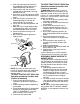
SAFETY RULES IMPORTANT: This cutting machine is capable of amputating hands and feet and throwing objects. Failure to observe the following safety instructions could result in serious injury or death. • Slow down before turning. • Never leave a running machine unattended. Always turn off blades, set parking brake, stop engine, and remove keys before dismounting. • Turn off blades when not mowing. • Stop engine before removing grass catcher or unclogging chute.
SAFETY RULES • Follow the manufacturer’s recommendations for wheel weights or counterweights to improve stability. • Use extra care with grass catchers or other attachments. These can change the stability of the machine. • Keep all movement on the slopes slow and gradual. Do not make sudden changes in speed or direction. • Avoid starting or stopping on a slope. If tires lose traction, disengage the blades and proceed slowly straight down the slope.
SAFETY RULES • Remove obstacles such as rocks, tree limbs, etc. • Watch for holes, ruts, or bumps. Uneven terrain could overturn the machine. Tall grass can hide obstacles. • Use slow speed. Choose a low gear so that you will not have to stop or shift while on the slope. • Avoid starting or stopping on a slope. If tires lose traction, disengage the blades and proceed slowly straight down the slope. • If machine stops while going uphill, disengage blades, shift into reverse and back down slowly.
PRODUCT SPECIFICATIONS Gasoline Capacity and Type: 5 Gallons Unleaded Regular Oil Type (API-SF-SJ): SAE 30 (above 32°F) SAE 5W-30 (Below 32°F) Oil Capacity: W/Filter: 4.0 Pints W/O Filter: 3.75 Pints Spark Plug: (Gap: .040") Champion QC12YC Ground Speed (MPH): Forward: Reverse: Tire Pressure: Front: 14 PSI Rear: 10 PSI Charging System: 16 Amps @ 3600RPM Battery: Amp/Hr: 35 Min. CCA: 280 Case Size: U1R Blade Bolt Torque: 45-55 Ft. Lbs.
UNASSEMBLED PARTS Steering Wheel Steering Sleeve (1) Locknut 1/2-20 Steering Wheel Adapter Steering Wheel Insert (1) Large Flat Washer Gauge Wheels (4) Adjusting Bar (4) Retainer Springs (double loop) (4) Clevis Pins (4) Wheels (4) Shoulder Bolt (4) Washers 3/8 x 3/4 x 14 Ga.
ASSEMBLY/PRE-OPERATION Your new tractor has been assembled at the factory with the exception of those parts left unassembled for shipping purposes. To ensure safe and proper operation of your tractor all parts and hardware you assemble must be tightened securely. Use the correct tools as necessary to insure proper tightness. Review the video cassette before you begin. Steering Wheel Insert TOOLS REQUIRED FOR ASSEMBLY A socket wrench set will make assembly easier.
2. Pivot seat upward and remove from the cardboard packing. Remove the cardboard packing and discard. 3. Place seat on seat pan so head of shoulder bolt is positioned over large slotted hole in pan. 4. Push down on seat to engage shoulder bolt in slot and pull seat towards rear of tractor. 5. Pivot seat and pan forward and assemble adjustment knob and flat washer loosely. Do not tighten. 6. Lower seat into operating position and sit in seat. 7.
Retainer Spring 6. Install belt into electric clutch pulley groove. 7. Place the suspension arms on outward pointing deck pins. Retain with double loop retainer spring with loops up as shown. 8. Install front plate assembly to tractor suspension brackets and retain with single loop retainer springs as shown. 9. Position front plate assembly between front mower brackets. Raise deck and plate assembly to align holes and insert flanged pins.
✔CHECKLIST 12. If equipped, turn height adjustment knob clockwise to remove slack from mower suspension. 13. Raise deck to highest position. 14. Adjust gauge wheels before operating mower as shown in the Operation section of this manual. Before you operate your new tractor, we wish to assure that you receive the best performance and satisfaction from this quality product. Please review the following checklist: ✓ All assembly instructions have been completed. ✓ No remaining loose parts in carton.
OPERATION These symbols may appear on your tractor or in literature supplied with the product. Learn and understand their meaning.
KNOW YOUR TRACTOR READ THIS OWNER'S MANUAL AND SAFETY RULES BEFORE OPERATING YOUR TRACTOR Compare the illustrations with your tractor to familiarize yourself with the locations of various controls and adjustments. Save this manual for future reference.
The operation of any tractor can result in foreign objects thrown into the eyes, which can result in severe eye damage. Always wear safety glasses or eye shields while operating your tractor or performing any adjustments or repairs. We recommend standard safety glasses or a wide vision safety mask worn over spectacles. 00155 IMPORTANT: Leaving the ignition switch in any position other than "STOP" will cause the battery to discharge and go dead.
TO OPERATE MOWER Your tractor is equipped with an operator presence sensing switch. Any attempt by the operator to leave the seat with the engine running and the attachment clutch engaged will shut off the engine. You must remain fully and centrally positioned in the seat to prevent the engine from hesitating or cutting off when operating your equipment on rough, rolling terrain or hills. 1. Select desired height of cut. 2. Lower mower with attachment lift control. 3.
TO TRANSPORT When pushing or towing your tractor, be sure to disengage transmission by placing freewheel control in freewheeling position. Freewheel control is located at the rear drawbar of tractor. 1. Raise attachment lift to highest position with attachment lift control. 2. Pull freewheel control out and into the slot and release so it is held in the disengaged position. • Do not push or tow tractor at more than two (2) MPH. • To re-engage transmission, reverse above procedure.
6. Insert key into ignition and turn key clockwise to start position and release key as soon as engine starts. Do not run starter continuously for more than fifteen seconds per minute. If the engine does not start after several attempts, push choke control in, wait a few minutes and try again. If engine still does not start, pull the choke control out and retry. WARM WEATHER STARTING (50° F and above) 7. When engine starts, slowly push choke control in until the engine begins to run smoothly.
7. Sitting in the tractor seat, start engine. After the engine is running, move throttle control to half (1/2) speed. Disengage parking brake. 8. Slowly move motion control lever forward, after the tractor moves approximately five (5) feet, slowly move motion control lever to reverse position. After the tractor moves approximately five (5) feet return the motion control lever to the neutral (N) position. Repeat this procedure with the motion control lever three (3) times.
MAINTENANCE MAINTENANCE SCHEDULE FILL IN DATES AS YOU COMPLETE REGULAR SERVICE E E RS S AG RS RS US OU SON OR UR OU HOU H T O H A 0 S E 8H SE RE 25 10 50 Y Y Y Y Y RE ER VER VER VER VER EFO FO V E B SERVICE E E E E E B H AC DATES Check Brake Operation Check Tire Pressure T R A C T 0 R Check Operator Presence and Interlock Systems Check for Loose Fasteners 5 Sharpen/Replace Mower Blades 3 Lubrication Chart Check Battery Level 4 Clean Battery and Terminals Check Transaxle Cooling Check V-Belts Chec
TRACTOR IMPORTANT: To ensure proper assembly, center hole in blade must align with star on mandrel assembly. 4. Install and tighten blade bolt securely (45-55 Ft. Lbs. torque). IMPORTANT: Special blade bolt is heat treated. Always observe safety rules when performing any maintenance. BRAKE OPERATION If tractor requires more than six (6) feet stopping distance at high speed in highest gear, then brake must be adjusted. (See “TO ADJUST BRAKE” in the Service and Adjustments section of this manual).
BATTERY V-BELTS Your tractor has a battery charging system which is sufficient for normal use. However, periodic charging of the battery with an automotive charger will extend its life. • Keep battery and terminals clean. • Keep battery bolts tight. • Keep small vent holes open. • Recharge at 6-10 amperes for 1 hour. NOTE: The original equipment battery on your tractor is maintenance free. Do not attempt to open or remove caps or covers. Adding or checking level of electrolyte is not necessary.
Oil Drain Valve Every 100 hours of operation (more often under extremely dusty, dirty conditions), remove the blower housing and other cooling shrouds. Clean the cooling fins and external surfaces as necessary. Make sure the cooling shrouds are reinstalled. NOTE: Operating the engine with a blocked grass screen, dirty or plugged cooling fins, and/or cooling shrouds removed will cause engine damage due to overheating.
SERVICE AND ADJUSTMENTS WARNING: TO AVOID SERIOUS INJURY, BEFORE PERFORMING ANY SERVICE OR ADJUSTMENTS: 1. Depress brake pedal fully and set parking brake. 2. Place attachment clutch in “DISENGAGED” position. 3. Turn ignition key to “STOP” and remove key. 4. Make sure the blades and all moving parts have completely stopped. 5. Disconnect spark plug wire from spark plug and place wire where it cannot come in contact with plug. TO REMOVE MOWER 1. Place attachment clutch in “DISENGAGED” position. 2.
NOTE: To assist in locating hole in flanged pin, the hole in pin is inline with notch on head of pin. If necessary, move mower side-to-side to give space between plate and mower brackets. IMPORTANT: Check belt for proper routing in all mower pulley grooves. 10. Engage belt tension rod by pushing rod into locking bracket. CAUTION: Belt tension rod is spring loaded. Have a tight grip on rod and engage slowly. 11.
TO REPLACE MOWER DRIVE BELT MOWER DRIVE BELT REMOVAL 1. Park tractor on a level surface. Engage parking brake. 2. Lower mower to its lowest position. 3. Disengage belt tension rod from lock bracket. CAUTION: Rod is spring loaded. Have a firm grip on rod and release slowly. 4. Remove screws from R.H. mandrel cover and remove cover. 5. Remove any dirt or grass clippings which may have accumulated around mandrels and entire upper deck surface. 6. Disconnect R.H.
13. Carefully roll belt over L.H. mandrel pulley. Make sure belt is in all grooves properly. Pull belt to front of mower to remove slack. 15. Reinstall mandrel covers and securely tighten all screws. 16. Carefully check belt routing making sure belt is in all grooves correctly. 17. Reinstall mower to tractor (See “TO INSTALL MOWER” in this section of manual). REINSTALL MOWER DRIVE BELT (Refer to “TO REMOVE MOWER DRIVE BELT” illustration in this section of manual). 14. Install belt into upper groove of R.
TO ADJUST STEERING WHEEL ALIGNMENT If steering wheel crossbars are not horizontal (left to right) when wheels are positioned straight forward, remove steering wheel and reassemble with crossbars horizontal. Tighten securely. FRONT WHEEL TOE-IN/CAMBER The front wheel toe-in and camber are not adjustable on your tractor. If damage has occurred to affect the front wheel toe-in or camber, contact a qualified service center. BELT INSTALLATION 1.
TO ATTACH JUMPER CABLES 1. Connect one end of the RED cable to the POSITIVE (+) terminal of each battery(A-B), taking care not to short against tractor chassis. 2. Connect one end of the BLACK cable to the NEGATIVE (-) terminal (C) of fully charged battery. 3. Connect the other end of the BLACK cable (D) to good chassis ground, away from fuel tank and battery. TO REMOVE CABLES, REVERSE ORDER 1. BLACK cable first from chassis and then from the fully charged battery. 2. RED cable last from both batteries.
STORAGE Immediately prepare your tractor for storage at the end of the season or if the tractor will not be used for 30 days or more. WARNING: Never store the tractor with gasoline in the tank inside a building where fumes may reach an open flame or spark. Allow the engine to cool before storing in any enclosure. TRACTOR Remove mower from tractor for winter storage. When mower is to be stored for a period of time, clean it thoroughly, remove all dirt, grease, leaves, etc. Store in a clean, dry area. 1.
TROUBLESHOOTING CHART: PROBLEM CAUSE CORRECTION Will not start 1. Out of fuel. 2. Engine not “CHOKED” properly. 3. Engine flooded. 1. Fill fuel tank. 2. See “TO START ENGINE” in Operation section. 3. Wait several minutes before attempting to start. 4. Bad spark plug. 4. Replace spark plug. 5. Dirty air filter. 5. Clean/replace air filter. 6. Dirty fuel filter. 6. Replace fuel filter. 7. Water in fuel. 7. Empty fuel tank and carburetor, refill tank with fresh gasoline and replace fuel filter. 8.
TROUBLESHOOTING CHART: PROBLEM CAUSE CORRECTION Loss of power (continued) 5. Low oil level/dirty oil. 6. Faulty spark plug. 5. Check oil level/change oil. 6. Clean and regap or change spark plug. 7. Dirty fuel filter. 7. Replace fuel filter. 8. Stale or dirty fuel. 8. Empty fuel tank and refill tank with fresh, clean gasoline. 9. Water in fuel. 9. Empty fuel tank and carburetor, refill tank with fresh gasoline and replace fuel filter. 10. Spark plug wire loose. 10. Connect and tighten spark plug wire.
TROUBLESHOOTING CHART: PROBLEM CAUSE CORRECTION Poor grass discharge 1. Engine speed too slow. Headlight(s) not working (if so equipped) 1. 2. 3. 4. 5. Battery will not charge 1. Bad battery cell(s). 2. Poor cable connections. 3. Faulty regulator (if so equipped). 4. Faulty alternator. Loss of drive 1. Place throttle control in “FAST” position. 2. Travel speed too fast. 2. Shift to slower speed. 3. Wet grass. 3. Allow grass to dry before mowing. 4. Mower deck not level. 4. Level mower deck. 5.
1. Fold this page along dotted line indicated above. 2. Hold page before you so that its left edge is vertically parallel to a tree trunk or other upright structure. 3. Sight across the fold in the direction of hill slope you want to measure. 4. Compare the angle of the fold with the slope of the hill. WARNING: To avoid serious injury, operate your tractor up and down the face of slopes, never across the face. Do not mow slopes greater than 15 degrees.