IMPORTANT MANUAL Do Not Throw Away 03076 OPERATOR'S MANUAL MODEL: PB24H48YT WARNING: Read this Manual and follow all Warnings and Safety Instructions. Failure to do so can result in serious injury. LAWN TRACTOR ALWAYS WEAR EYE PROTECTION DURING OPERATION Visit our website: www.poulan-pro.com 404402 02.09.06 VB Printed in U.S.A.
SAFETY RULES Safe Operation Practices for Ride-On Mowers DANGER: THIS CUTTING MACHINE IS CAPABLE OF AMPUTATING HANDS AND FEET AND THROWING OBJECTS. FAILURE TO OBSERVE THE FOLLOWING SAFETY INSTRUCTIONS COULD RESULT IN SERIOUS INJURY OR DEATH. • WARNING: In order to prevent accidental starting when setting up, transporting, adjusting or making repairs, always disconnect spark plug wire and place wire where it cannot contact spark plug.
SAFETY RULES Safe Operation Practices for Ride-On Mowers III. CHILDREN GENERAL SERVICE • Never operate machine in a closed area. • Keep all nuts and bolts tight to be sure the equipment is in safe working condition. • Never tamper with safety devices. Check their proper operation regularly. • Keep machine free of grass, leaves, or other debris build-up. Clean oil or fuel spillage and remove any fuelsoaked debris. Allow machine to cool before storing.
PRODUCT SPECIFICATIONS Gasoline Capacity and type: 3 Gallons Unleaded Regular Oil Type (API-SG-SL): SAE 30 (above 32°F) SAE 5W-30 (below 32°F) Oil Capacity: W/ Filter: W/O Filter: Spark Plug: (Gap: .040") Champion QC12YC Ground Speed (MPH): Forward: Reverse: Charging System: 16 AMPS @ 3600 RPM Battery: AMP/HR: MIN. CCA: Case Size: Blade Bolt Torque: 45-55FT. LBS. CUSTOMER RESPONSIBILITIES • • • 4.0 Pints 3.75 Pints Read and observe the safety rules.
UNASSEMBLED PARTS Slope Sheet Key (1) Oil Drain Tube (2) Keys ASSEMBLY Your new tractor has been assembled at the factory with the exception of those parts left unassembled for shipping puposes. When right or left hand is mentioned in this manual, it means when you are in the operating position (seated behind the steering wheel). ADJUST SEAT (See Fig. 2) • • TO REMOVE TRACTOR FROM CARTON • Sit in seat.
ASSEMBLY • • • Release parking brake by depressing brake pedal. Place freewheel control in disengaged position to disengage transmission (See “TO TRANSPORT” in the Operation section of this manual). Roll tractor forward off skid. ✓CHECKLIST BEFORE YOU OPERATE YOUR NEW TRACTOR, WE WISH TO ASSURE THAT YOU RECEIVE THE BEST PERFORMANCE AND SATISFACTION FROM THIS QUALITY PRODUCT. PLEASE REVIEW THE FOLLOWING CHECKLIST: ✓ All assembly instructions have been completed. ✓ No remaining loose parts in carton.
OPERATION These symbols may appear on your tractor or in literature supplied with the product. Learn and understand their meaning.
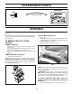
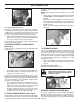
OPERATION KNOW YOUR TRACTOR READ THIS OWNER'S MANUAL AND SAFETY RULES BEFORE OPERATING YOUR TRACTOR Compare the illustrations with your tractor to familiarize yourself with the locations of various controls and adjustments. Save this manual for future reference. G E P D H K L B J N F C A M FIG. 3 Our tractors conform to the applicable safety standards of the American National Standards Institute. (H) LIGHT SWITCH – Turns the headlights on and off.
OPERATION The operation of any tractor can result in foreign objects thrown into the eyes, which can result in severe eye damage. Always wear safety glasses or eye shields while operating your tractor or performing any adjustments or repairs. We recommend standard safety glasses or a wide vision safety mask worn over spectacles. IMPORTANT: Leaving the ignition switch in any position other than "STOP" will cause the battery to discharge and go dead.
OPERATION in proper position to help prevent scalping in most terrain conditions. NOTE: Adjust gauge wheels with tractor on a flat level surface. • Adjust mower to desired cutting height (See “TO ADJUST MOWER CUTTING HEIGHT” in this section of manual). • With mower in desired height of cut position, gauge wheels should be assembled so they are slightly off the ground. Install gauge wheel in appropriate hole. Tighten securely. • Repeat for all, installing gauge wheel in same adjustment hole. J K L FIG.
OPERATION WARNING: Backing up with the attachment clutch engaged while mowing is strongly discouraged. Turning the ROS "ON", to allow reverse operation with the attachment clutch engaged, should only be done when the operator decides it is necessary to reposition the machine with the attachment engaged. Do not mow in reverse unless absolutely necessary. Transmission Engaged USING THE REVERSE OPERATION SYSTEM Only use if you are certain no children or other bystanders will enter the mowing area.
OPERATION • Release the parking brake and let the brake slowly return to operating position. • Allow one minute for transmission to warm up. This can be done during the engine warm up period. • The attachments can be used during the engine warm-up period after the transmission has been warmed up and may require the choke control be pulled out slightly.
OPERATION MOWING TIPS • • • • Mower should be properly leveled for best mowing performance. See “TO LEVEL MOWER HOUSING” in the Service and Adjustments section of this manual. The left hand side of mower should be used for trimming. Drive so that clippings are discharged onto the area that has been cut. Have the cut area to the right of the machine. This will result in a more even distribution of clippings and more uniform cutting.
MAINTENANCE MAINTENANCE SCHEDULE BEFORE EACH USE EVERY 8 HOURS EVERY 25 HOURS EVERY 50 HOURS EVERY 100 HOURS EVERY SEASON BEFORE STORAGE Check Brake Operation Check Tire Pressure T Check Operator Presence & ROS Systems R A Check for Loose Fasteners C Check/Replace Mower Blades T Lubrication Chart 0 Check Battery Level R Clean Battery and Terminals 3 4 Check Transaxle Cooling Check Mower Levelness Check V-Belts Check Engine Oil Level Change Engine Oil (with oil filter) 1,2 Change Engine Oil (wi
MAINTENANCE TRACTOR CAUTION: Use only a replacement blade approved by the manufacturer of your tractor. Using a blade not approved by the manufacturer of your tractor is hazardous, could damage your tractor and void your warranty. Always observe safety rules when performing any maintenance. BRAKE OPERATION If tractor requires more than five (5) feet to stop at highest speed in highest gear on a level, dry concrete or paved surface, then brake must be serviced.
MAINTENANCE V-BELTS • Check V-belts for deterioration and wear after 100 hours of operation and replace if necessary. The belts are not adjustable. Replace belts if they begin to slip from wear. OIL DRAIN VALVE TRANSAXLE COOLING CLOSED AND LOCKED POSITION The transmission fan and cooling fins should be kept clean to assure proper cooling. Do not attempt to clean fan or transmission while engine is running or while the transmission is hot.
MAINTENANCE MUFFLER CLAMP Inspect and replace corroded muffler and spark arrester (if equipped) as it could create a fire hazard and/or damage. FUEL FILTER SPARK PLUGS FIG. 16 Replace spark plugs at the beginning of each mowing season or after every 100 hours of operation, whichever occurs first. Spark plug type and gap setting are shown in “PRODUCT SPECIFICATIONS” section of this manual. • IN-LINE FUEL FILTER (See Fig.
SERVICE AND ADJUSTMENTS WARNING: TO AVOID SERIOUS INJURY, BEFORE PERFORMING ANY SERVICE OR ADJUSTMENTS: • Depress brake pedal fully and set parking brake. • Place attachment clutch in “DISENGAGED” position. • Turn ignition key to “STOP” and remove key. • Make sure the blades and all moving parts have completely stopped. • Disconnect spark plug wire from spark plug and place wire where it cannot come in contact with plug. TRACTOR (See Fig.
SERVICE AND ADJUSTMENTS D 02965 02 05 1 02996 FIG. 19 NOTE: Be sure mower side suspension arms (A) are pointing forward before sliding mower under tractor. • Slide mower under tractor until it is centered under tractor. • ATTACH MOWER SIDE SUSPENSION ARMS (A) TO CHASSIS - Position hole in arm over pin (B) on outside of tractor chassis and secure with washer and retainer spring. A 02965 NOTE: Be sure mower side suspension arms (A) are pointing forward before sliding mower under tractor.
SERVICE AND ADJUSTMENTS • • • • TO LEVEL MOWER Repeat on opposite side of tractor. Turn steering wheel to position wheels straight forward. ATTACH FRONT LINK (E) - Work from left side of tractor. Insert rod end of link assembly through front hole in tractor front suspension bracket (F) and secure with retainer spring (G) through hole in link located behind the bracket. Insert other end of link (E) into hole in front mower bracket (H) and secure with washer and retainer spring (J).
SERVICE AND ADJUSTMENTS B M L F K A E H C D FIG. 25 PRECISION SIDE-TO-SIDE ADJUSTMENT • (See Fig. 26) • With all tires properly inflated, park tractor on level • ground or driveway. • CAUTION: Blades are sharp. Protect your hands with gloves and/or wrap blade with heavy cloth. • • • • Raise mower to its highest position. At both sides of mower, position blade at side and measure the distance (A) from bottom edge of blade to the ground. The distance should be the same on both sides.
SERVICE AND ADJUSTMENTS NOTE: Each full turn of the adjustment nut will change mower height about 1/8". • Recheck measurements, adjust if necessary until front tip of blade is 1/8" to 1/2" lower than the rear tip. • Hold adjustment nut in position with wrench and tighten jam nut securely against adjustment nut. TO REPLACE MOTION DRIVE BELT (See Fig. 30) TO REPLACE MOWER BLADE DRIVE BELT (See Fig. 29) BELT REMOVAL • Remove mower (See “TO REMOVE MOWER” in this section of manual).
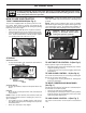
SERVICE AND ADJUSTMENTS NOTE: To seal tire punctures and prevent flat tires due to slow leaks, tire sealant may be purchased from your local parts dealer. Tire sealant also prevents tire dry rot and corrosion. G WASHERS H B RETAINING RING A AXLE COVER C J D E SQUARE KEY (REAR WHEEL ONLY) FIG. 31 F TO START ENGINE WITH A WEAK BATTERY (See Fig. 32) 02953 electric WARNING: Lead-acid batteries generate explosive gases. Keep sparks, flame and smoking materials away from batteries.
SERVICE AND ADJUSTMENTS TO REPLACE HEADLIGHT BULB • • • • WEAK OR DEAD BATTERY INTERLOCKS AND RELAYS FULLY CHARGED BATTERY Loose or damaged wiring may cause your tractor to run poorly, stop running, or prevent it from starting. • Check wiring. See electrical wiring diagram in the Repair Parts section. FIG. 32 REPLACING BATTERY (See Fig. 33) TO REPLACE FUSE WARNING: Do not short battery terminals by allowing a wrench or any other object to contact both terminals at the same time.
STORAGE Immediately prepare your tractor for storage at the end of the season or if the tractor will not be used for 30 days or more. ENGINE FUEL SYSTEM IMPORTANT: IT IS IMPORTANT TO PREVENT GUM DEPOSITS FROM FORMING IN ESSENTIAL FUEL SYSTEM PARTS SUCH AS CARBURETOR, FUEL FILTER, FUEL HOSE, OR TANK DURING STORAGE. ALSO, EXPERIENCE INDICATES THAT ALCOHOL BLENDED FUELS (CALLED GASOHOL OR USING ETHANOL OR METHANOL) CAN ATTRACT MOISTURE WHICH LEADS TO SEPARATION AND FORMATION OF ACIDS DURING STORAGE.
TROUBLESHOOTING POINTS PROBLEM Will not start Hard to start CAUSE 1. 2. 3. 4. 5. 6. 7. 8. CORRECTION Out of fuel. Engine not “CHOKED” properly. Engine flooded. Bad spark plug. Weak or dead battery. Dirty air filter. Dirty fuel filter. Water in fuel. 1. 2. 3. 4. 5. 6. 7. 8. 9. 10. Loose or damaged wiring. Carburetor out of adjustment. 9. 10. 11. Engine valves out of adjustment. 11. Fill fuel tank. See “TO START ENGINE” in Operation section. Wait several minutes before attempting to start.
TROUBLESHOOTING POINTS PROBLEM CAUSE CORRECTION Engine dies when tractor is shifted into reverse 1. 1. Turn ignition key to ROS "ON" position. See Operation section. Reverse operation system (ROS) is not "ON" while mower or other attachment is engaged. Engine continues to run when operator leaves seat with attachment clutch engaged 1. Faulty operator-safety presence control system. 1. Check wiring, switches and connections. If not corrected, contact an authorized service center/ department.
LIMITED WARRANTY The Manufacturer warrants to the original consumer purchaser that this product as manufactured is free from defects in materials and workmanship. For a period of two (2) years from date of purchase by the original consumer purchaser, we will repair or replace, at our option, without charge for parts or labor incurred in replacing parts, any part which we find to be defective due to materials or workmanship. This Warranty is subject to the following limitations and exclusions. 1.
SUGGESTED GUIDE FOR SIGHTING SLOPES FOR SAFE OPERATION FO L D AL ONG THIS DOT IS A TED 15 D LINE EGR EE S LOP E 29 ONLY RIDE UP AND DOWN HILL, NOT ACROSS HILL 15 DEGREES MAX. WARNING: To avoid serious injury, operate your tractor up and down the face of slopes, never across the face. Do not mow slopes greater than 15 degrees. Make turns gradually to prevent tipping or loss of control. Exercise extreme caution when changing direction on slopes. 1. Fold this page along dotted line indicated above. 2.
PARTS AND SERVICE This product has been expertly engineered and carefully manufactured to rigid quality standards. As with all mechanical products, some adjustments or part replacement may be necessary during the life of your unit. For Parts and service, contact our authorized distributor: call 1-800-849-1297 • For replacement parts, have available the following information: a. Model Number/Manufacturer's I.D. Number b. Description of part.