IMPORTANT MANUAL Do Not Throw Away 02478 OWNER'S MANUAL MODEL: WARNING: Read this Owner's Manual and follow all Warnings and Safety Instructions. Failure to do so can result in serious injury. PD20H42STA LAWN TRACTOR ALWAYS WEAR EYE PROTECTION DURING OPERATION 184617 Rev. 2 02.06.03 TR Printed in U.S.A.
SAFETY RULES SAFE OPERATION PRACTICES FOR RIDE-ON MOWERS IMPORTANT: THIS CUTTING MACHINE IS CAPABLE OF AMPUTATING HANDS AND FEET AND THROWING OBJECTS. FAILURE TO OBSERVE THE FOLLOWING SAFETY INSTRUCTIONS COULD RESULT IN SERIOUS INJURY OR DEATH. DO NOT: • Do not turn on slopes unless necessary, and then, turn slowly and gradually downhill, if possible. • Do not mow near drop-offs, ditches, or embankments.
SAFETY RULES SAFE OPERATION PRACTICES FOR RIDE-ON MOWERS IMPORTANT: THIS CUTTING MACHINE IS CAPABLE OF AMPUTATING HANDS AND FEET AND THROWING OBJECTS. FAILURE TO OBSERVE THE FOLLOWING SAFETY INSTRUCTIONS COULD RESULT IN SERIOUS INJURY OR DEATH. • • • • • • • • • • • • • • Be sure the area is clear of other people before mowing. Stop machine if anyone enters the area. Never carry passengers or children even with the blades off. Do not mow in reverse unless absolutely necessary.
CONGRATULATIONS on your purchase of a new tractor. It has been designed, engineered and manufactured to give you the best possible dependability and performance. Should you experience any problem you cannot easily remedy, please contact your nearest authorized service center/ department. We have competent, well-trained technicians and the proper tools to service or repair this tractor. Please read and retain this manual. The instructions will enable you to assemble and maintain your tractor properly.
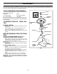
UNASSEMBLED PARTS Seat Steering Wheel Steering Wheel Insert (1) Washer 17/32 x 1-3/16 x 12 Gauge (1) Knob Steering Extension Shaft Steering Sleeve Slope Sheet Steering Adapter (1) Large Flat Washer (1) Oil Drain Tube (1) Locknut 1/2-20 (2) Keys (2) Mulch Blades (1) Hex Bolt 1/4-28 x 1-1/4 (1) Locknut 1/4-28 5
ASSEMBLY Your new tractor has been assembled at the factory with exception of those parts left unassembled for shipping purposes. To ensure safe and proper operation of your tractor all parts and hardware you assemble must be tightened securely. Use the correct tools as necessary to insure proper tightness. TOOLS REQUIRED FOR ASSEMBLY INSERT A socket wrench set will make assembly easier. Standard wrench sizes are listed.
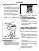
ASSEMBLY HOW TO SET UP YOUR TRACTOR SEAT PAN INSTALL SEAT (See Fig. 2) LABEL Adjust seat before tightening adjustment knob. • Remove adjustment knob and flat washer securing seat to cardboard packing and set aside for assembly of seat to tractor. • Pivot seat upward and remove from the cardboard packing. Remove the cardboard packing and discard. • Place seat on seat pan so head of shoulder bolt is positioned over large slotted hole in pan.
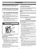
ASSEMBLY IMPORTANT: FOR SHIPPING PURPOSES, THE MULCHER PLATE WAS PREATTACHED TO YOUR MOWER.THE MULCHER PLATE MUST ONLY BE USED WITH THE MULCHING BLADES THAT CAME PACKED SEPARATELY IN THE CARTON. • CHECK DECK LEVELNESS For best cutting results, mower housing should be properly leveled. See “TO LEVEL MOWER HOUSING” in the Service and Adjustments section of this manual. YOUR MOWER CAME FACTORY EQUIPPED WITH HIGH PERFORMANCE BLADES, WHICH ARE THE BEST BLADES FOR BAGGING AND DISCHARGING.
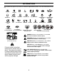
OPERATION These symbols may appear on your tractor or in literature supplied with the product. Learn and understand their meaning.
OPERATION KNOW YOUR TRACTOR READ THIS OWNER'S MANUAL AND SAFETY RULES BEFORE OPERATING YOUR TRACTOR Compare the illustrations with your tractor to familiarize yourself with the locations of various controls and adjustments. Save this manual for future reference.
OPERATION The operation of any tractor can result in foreign objects thrown into the eyes, which can result in severe eye damage. Always wear safety glasses or eye shields while operating your tractor or performing any adjustments or repairs. We recommend a wide vision safety mask over spectacles or standard safety glasses. HOW TO USE YOUR TRACTOR • TO SET PARKING BRAKE (See Fig. 6) IMPORTANT:LEAVING THE IGNITION SWITCH IN ANY POSITION OTHER THAN "OFF" WILL CAUSE THE BATTERY TO BE DISCHARGED, (DEAD).
OPERATION • For best cutting performance, grass over 6 inches in height should be mowed twice. Make the first cut relatively high; the second to desired height. "ENGAGED" POSITION ATTACHMENT LIFT LEVER HIGH POSITION TO ADJUST GAUGE WHEELS (See Fig. 7) ATTACHMENT CLUTCH LEVER "DISENGAGED" POSITION Gauge wheels are properly adjusted when they are slightly off the ground when mower is at the desired cutting height in operating position.
OPERATION Transmission Engaged CAUTION: Alcohol blended fuels (called gasohol or using ethanol or methanol) can attract moisture which leads to separation and formation of acids during storage. Acidic gas can damage the fuel system of an engine while in storage. To avoid engine problems, the fuel system should be emptied before storage of 30 days or longer. Drain the gas tank, start the engine and let it run until the fuel lines and carburetor are empty. Use fresh fuel next season.
OPERATION AUTOMATIC TRANSMISSION WARM UP • Before driving the unit in cold weather, the transmission should be warmed up as follows: • Be sure the tractor is on level ground. • Place the motion control lever in neutral. Release the parking brake and let the clutch/brake slowly return to operating position. • Allow one minute for transmission to warm up. This can be done during the engine warm up period.
OPERATION MULCHING MOWING TIPS IMPORTANT: FOR BEST PERFORMANCE, KEEP MOWER HOUSING FREE OF BUILT-UP GRASS AND TRASH. CLEAN AFTER EACH USE. • • • MAX 1/3 The special mulching blade will recut the grass clippings many times and reduce them in size so that as they fall onto the lawn they will disperse into the grass and not be noticed. Also, the mulched grass will biodegrade quickly to provide nutrients for the lawn.
MAINTENANCE MAINTENANCE SCHEDULE FILL IN DATES AS YOU COMPLETE REGULAR SERVICE E E S S RS S AG US UR OUR OU SON OR H UR O H C T O H H A 0 S EA 8H SE RE 25 50 10 Y Y Y Y Y RE O R R R R R O F E E E E E F BE SERVICE EV EV EV EV EV BE DATES Check Brake Operation Check Tire Pressure T R A C T 0 R Check Operator Presence and Interlock Systems Check for Loose Fasteners 5 Sharpen/Replace Mower Blades 3 Lubrication Chart Check Battery Level 4 Clean Battery and Terminals Check Transaxle Cooling Check V-Bel
MAINTENANCE TRACTOR MANDREL ASSEMBLY TRAILING EDGE UP BLADE Always observe safety rules when performing any maintenance. CENTER HOLE BRAKE OPERATION If tractor requires more than six (6) feet stopping distance at high speed in highest gear, then brake must be adjusted. (See “TO ADJUST BRAKE” in the Service and Adjustments section of this manual). FLAT WASHER LOCK WASHER STAR TIRES • Maintain proper air pressure in all tires (See “PRODUCT SPECIFICATIONS” section of this manual).
MAINTENANCE NOTE: Although multi-viscosity oils (5W30, 10W30 etc.) improve starting in cold weather, these multi-viscosity oils will result in increased oil consumption when used above 32°F. Check your engine oil level more frequently to avoid possible engine damage from running low on oil. Change the oil after every 50 hours of operation or at least once a year if the tractor is not used for 50 hours in one year.
MAINTENANCE CLEAN AIR SCREEN ENGINE OIL FILTER Air screen must be kept free of dirt and chaff to prevent engine damage from overheating. Clean with a wire brush or compressed air to remove dirt and stubborn dried gum fibers. Replace the engine oil filter every season or every other oil change if the tractor is used more than 100 hours in one year.
SERVICE AND ADJUSTMENTS WARNING: TO AVOID SERIOUS INJURY, BEFORE PERFORMING ANY SERVICE OR ADJUSTMENTS • Depress clutch/brake pedal fully and set parking brake. • Place motion control lever in neutral (N) position. • Place attachment clutch in “DISENGAGED” position. • Turn ignition key to “STOP” and remove key. • Make sure the blades and all moving parts have completely stopped. • Disconnect spark plug wire from spark plug and place wire where it cannot come in contact with plug.
SERVICE AND ADJUSTMENTS • TO LEVEL MOWER HOUSING Adjust the mower while tractor is parked on level ground or driveway. Make sure tires are properly inflated (See “PRODUCT SPECIFICATIONS” section of this manual). If tires are over or underinflated, you will not properly adjust your mower. • • • SIDE-TO-SIDE ADJUSTMENT (See Figs. 19 and 20) • Raise mower to its highest position. • At the midpoint of both sides of mower, measure height from bottom edge of mower to ground.
SERVICE AND ADJUSTMENTS • TO REPLACE MOWER BLADE DRIVE BELT (See Fig. 23) The mower blade drive belt may be replaced without tools. Park the tractor on level surface. Engage parking brake. BELT REMOVAL • Remove mower from tractor (See “TO REMOVE MOWER” in this section of manual). • Work belt off both mandrel pulleys and idler pulleys. • Pull belt away from mower. BELT INSTALLATION • Work belt around both mandrel pulleys and idler pulleys.
SERVICE AND ADJUSTMENTS ENGINE PULLEY NEUTRAL LOCK GATE MOTION CONTROL LEVER CLUTCHING IDLER STATIONARY IDLER ADJUSTMENT BOLT FIG. 26 TRANSMISSION INPUT PULLEY TO AD JUST STEER ING WHEEL ALIGNMENT CENTER SPAN KEEPER If steering wheel crossbars are not horizontal (left to right) when wheels are positioned straight forward, remove steering wheel and reassemble per instructions in the Assembly section of this manual. FRONT WHEEL TOE-IN/CAMBER FIG.
SERVICE AND ADJUSTMENTS • TO START ENGINE WITH A WEAK BATTERY (See Fig. 28) • WARNING: Lead-acid batteries generate explosive gases. Keep sparks, flame and smoking materials away from batteries. Always wear eye protection when around batteries. • If your battery is too weak to start the engine, it should be recharged. (See "BATTERY" in the MAINTENANCE section of this manual).
SERVICE AND ADJUSTMENTS TO REMOVE HOOD AND GRILL ASSEMBLY (See Fig. 31) • • • • TO ADJUST CARBURETOR Your carburetor is not adjustable. If your engine does not operate properly due to suspected carburetor problems, take your tractor to an authorized service center for repair and/or adjustment. High speed stop is factory adjusted. Do not adjust - damage may result. Raise hood. Unsnap headlight wire connector. Stand in front of tractor. Grasp hood at sides, tilt toward engine and lift off of tractor.
STORAGE Immediately prepare your tractor for storage at the end of the season or if the tractor will not be used for 30 days or more. ENGINE FUEL SYSTEM IMPORTANT: IT IS IMPORTANT TO PREVENT GUM DEPOSITS FROM FORMING IN ESSENTIAL FUEL SYSTEM PARTS SUCH AS CARBURETOR, FUEL FILTER, FUEL HOSE, OR TANK DURING STORAGE. ALSO, EXPERIENCE INDICATES THAT ALCOHOL BLENDED FUELS (CALLED GASOHOL OR USING ETHANOL OR METHANOL) CAN ATTRACT MOISTURE WHICH LEADS TO SEPARATION AND FORMATION OF ACIDS DURING STORAGE.
TROUBLESHOOTING POINTS PROBLEM Will not start CAUSE 1. 2. 3. 4. 5. 6. 7. Out of fuel. Engine not “CHOKED” properly. Engine flooded. Bad spark plug. Dirty air filter. Dirty fuel filter. Water in fuel. 1. 2. 3. 4. 5. 6. 7. 8. 9. Loose or damaged wiring. Carburetor out of adjustment. 8. 9. 10. Hard to start CORRECTION Engine valves out of adjustment. 10. Fill fuel tank. See “TO START ENGINE” in Operation section. Wait several minutes before attempting to start. Replace spark plug.
TROUBLESHOOTING POINTS PROBLEM CAUSE CORRECTION Engine continues to run when operator leaves seat with attachment clutch engaged 1. Faulty operator-safety presence control system. 1. Check wiring, switches and connections. If not corrected, contact an authorized service center/ department. Poor cut - uneven 1. 2. 3. 4. 5. Worn, bent or loose blade. Mower deck not level. Buildup of grass, leaves, and trash under mower. Bent blade mandrel.
TRACTOR - - MODEL NUMBER PD20H42STA PRODUCT NO. 954 56 95-09 SCHEMATIC RED BLACK BATTERY RED A RED FUSE AMMETER (OPTIONAL) M STARTER BLACK WHITE SOLENOID RED B S G BLACK L M CLUTCH / BRAKE (PEDAL UP) A1 A2 WHITE SEAT SWITCH (NOT OCCUPIED) IGNITION SWITCH WHITE BLACK BLACK BLACK BLACK HOUR METER ATT'MENT CLUTCH (CLUTCH OFF) GROUNDING CONNECTOR (OPTIONAL) BLUE SPARK PLUG GAP (2 PLUGS ON TWIN CYL.
TRACTOR - - MODEL NUMBER PD20H42STA PRODUCT NO. 954 56 95-09 ELECTRICAL 22 21 42 24 41 43 27 27 40 26 27 27 25 16 16 33 30 D.C .
TRACTOR - - MODEL NUMBER PD20H42STA PRODUCT NO. 954 56 95-09 ELECTRICAL KEY NO. 1 2 8 16 21 22 24 25 26 27 28 29 30 33 40 41 42 43 45 52 90 PART NO.
TRACTOR - - MODEL NUMBER PD20H42STA PRODUCT NO.
TRACTOR - - MODEL NUMBER PD20H42STA PRODUCT NO. 954 56 95-09 CHASSIS KEY NO. PART NO.
TRACTOR - - MODEL NUMBER PD20H42STA PRODUCT NO.
TRACTOR - - MODEL NUMBER PD20H42STA PRODUCT NO. 954 56 95-09 DRIVE KEY NO. PART NO.
TRACTOR - - MODEL NUMBER PD20H42STA PRODUCT NO.
TRACTOR - - MODEL NUMBER PD20H42STA PRODUCT NO. 954 56 95-09 STEERING ASSEMBLY KEY NO. PART NO.
TRACTOR - - MODEL NUMBER PD20H42STA PRODUCT NO. 954 56 95-09 SEAT ASSEMBLY 1 8 8 9 14 9 7 7 10 5 6 22 21 2 24 5 16 25 15 11 4 13 17 KEY NO. 1 2 3 4 5 6 7 8 9 10 11 12 PART NO. 171683 140551 71110616 19131610 145006 73800600 124181X 17000616 19131614 182493 166369 121246X 3 12 DESCRIPTION Seat Bracket Pivot Seat 8 720 Bolt Fin Hex 3/8-16unc X 1 Washer 13/32 X 1 X 10 Ga Clip Push-In Nut Hex w/Ins. 3/8-16 Unc Spring Seat Cprsn 2 250 Blk Zi Screw 3/8-16 x 1.5 Smgml Washer 13/32 X 1 X 14 Ga.
TRACTOR - - MODEL NUMBER PD20H42STA PRODUCT NO. 954 56 95-09 DECALS 2 7 11 16 4 4 3 10 2 20 9 1 8 6 12 5 14 KEY NO. 1 2 3 4 5 6 7 8 9 10 11 12 PART NO.
TRACTOR - - MODEL NUMBER PD20H42STA PRODUCT NO.
TRACTOR - - MODEL NUMBER PD20H42STA PRODUCT NO. 954 56 95-09 ENGINE KEY NO. PART NO. 1 2 3 170771 17720408 ------- 4 5 6 8 10 13 14 16 17 23 25 26 29 31 32 33 37 38 41 44 45 46 72 81 112 149723 160589 159955 171877 162797 165391 148456 11050600 17060624 169837 145996 73920600 137180 185534 140527 123487X 137040 181654 139277 17670412 17000612 19091416 183906 73510400 3645J NOTE: DESCRIPTION Control, Throttle Screw Hex Thd Cut 1/4-20 x 1/2 Engine Briggs Model 407777 (Order Parts from Engine Mfg.
TRACTOR - - MODEL NUMBER PD20H42STA PRODUCT NO.
TRACTOR - - MODEL NUMBER PD20H42STA PRODUCT NO. 954 56 95-09 MOWER DECK KEY NO. PART NO. 1 2 3 4 5 6 8 9 10 182032X421 72140506 138017 165460 4939M 178024 850857 10030600 140296 11 134149 DESCRIPTION Mower Deck Assembly, 42" Bolt Bracket Asm Fr.
TRACTOR - - MODEL NUMBER PD20H42STA PRODUCT NO.
TRACTOR - - MODEL NUMBER PD20H42STA PRODUCT NO. 954 56 95-09 MOWER LIFT KEY NO. PART NO.
LIMITED WARRANTY The Manufacturer warrants to the original consumer purchaser that this product as manufactured is free from defects in materials and workmanship. For a period of two (2) years from date of purchase by the original consumer purchaser, we will repair or replace, at our option, without charge for parts or labor incurred in replacing parts, any part which we find to be defective due to materials or workmanship. This Warranty is subject to the following limitations and exclusions. 1.
SUGGESTED GUIDE FOR SIGHTING SLOPES FOR SAFE OPERATION FO L D AL ONG THIS DOT IS A TED 15 D LINE E GR EE S LO P E 47 ONLY RIDE UP AND DOWN HILL, NOT ACROSS HILL 15 DEGREES MAX. WARNING: To avoid serious injury, operate your tractor up and down the face of slopes, never across the face. Do not mow slopes greater than 15 degrees. Make turns gradually to prevent tipping or loss of control. Exercise extreme caution when changing direction on slopes. 1. Fold this page along dotted line indicated above. 2.
PARTS AND SERVICE Your POULAN PRO product has been expertly engineered and carefully manufactured to rigid quality standards. As with all mechanical products, some adjustments or part replacement may be necessary during the life of your unit. FOR SERVICE OR REPLACEMENT PARTS: 1. Consult your dealer/place of purchase. 2. Consult the yellow pages of your phone directory for the name of the nearest service dealer (under “saws” for Chain Saws or under “lawn mowers” for Trimmers, Brushcutters, and Blowers). 3.