IMPORTANT MANUAL Do Not Throw Away 00993-poulan_pro 02478 OWNER'S MANUAL MODEL: WARNING: Read this Owner's Manual and follow all Warnings and Safety Instructions. Failure to do so can result in serious injury. PDB1842STA LAWN TRACTOR ALWAYS WEAR EYE PROTECTION DURING OPERATION 187733 04.10.03 TR Printed in U.S.A.
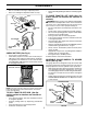
SAFETY RULES SAFE OPERATION PRACTICES FOR RIDE-ON MOWERS IMPORTANT: THIS CUTTING MACHINE IS CAPABLE OF AMPUTATING HANDS AND FEET AND THROWING OBJECTS. FAILURE TO OBSERVE THE FOLLOWING SAFETY INSTRUCTIONS COULD RESULT IN SERIOUS INJURY OR DEATH. DO NOT: • Do not turn on slopes unless necessary, and then, turn slowly and gradually downhill, if possible. • Do not mow near drop-offs, ditches, or embankments.
SAFETY RULES SAFE OPERATION PRACTICES FOR RIDE-ON MOWERS IMPORTANT: THIS CUTTING MACHINE IS CAPABLE OF AMPUTATING HANDS AND FEET AND THROWING OBJECTS. FAILURE TO OBSERVE THE FOLLOWING SAFETY INSTRUCTIONS COULD RESULT IN SERIOUS INJURY OR DEATH. • • • • • • • • • • • • • • Be sure the area is clear of other people before mowing. Stop machine if anyone enters the area. Never carry passengers or children even with the blades off. Do not mow in reverse unless absolutely necessary.
CONGRATULATIONS on your purchase of a new tractor. It has been designed, engineered and manufactured to give you the best possible dependability and performance. Should you experience any problem you cannot easily remedy, please contact your nearest authorized service center/ department. We have competent, well-trained technicians and the proper tools to service or repair this tractor. Please read and retain this manual. The instructions will enable you to assemble and maintain your tractor properly.
UNASSEMBLED PARTS Seat Steering Wheel Steering Wheel Insert (1) Washer 17/32 x 1-3/16 x 12 Gauge (1) Knob Steering Extension Shaft Gauge Wheel (4) Adjusting Bar Steering Sleeve (4) Wheels (4) Clevis Pins (4) Retainer Springs (double loop) Steering Adapter (4) Washers 3/8 x 3/4 x 14 Ga.
ASSEMBLY Your new tractor has been assembled at the factory with exception of those parts left unassembled for shipping purposes. To ensure safe and proper operation of your tractor all parts and hardware you assemble must be tightened securely. Use the correct tools as necessary to insure proper tightness. TOOLS REQUIRED FOR ASSEMBLY INSERT A socket wrench set will make assembly easier. Standard wrench sizes are listed.
ASSEMBLY • • Get off seat without moving its adjusted position. Raise seat and tighten adjustment knob securely. • TO DRIVE TRACTOR OFF SKID (See Operation section for location and function of controls) SEAT WARNING: Before starting, read, understand and follow all instructions in the Operation section of this manual. Be sure tractor is in a well-ventilated area. Be sure the area in front of tractor is clear of other people and objects. • Be sure all the above assembly steps have been completed.
ASSEMBLY IMPORTANT: FOR SHIPPING PURPOSES, THE MULCHER PLATE WAS PREATTACHED TO YOUR MOWER.THE MULCHER PLATE MUST ONLY BE USED WITH THE MULCHING BLADES THAT CAME PACKED SEPARATELY IN THE CARTON. YOUR MOWER CAME FACTORY EQUIPPED WITH HIGH PERFORMANCE BLADES, WHICH ARE THE BEST BLADES FOR BAGGING AND DISCHARGING. TO USE YOUR MOWER WITH THE HIGH PERFORMANCE BLADES THE MULCHER PLATE MUST BE REMOVED FROM THE MOWER (SEE FIG. 4B).
OPERATION These symbols may appear on your tractor or in literature supplied with the product. Learn and understand their meaning.
OPERATION KNOW YOUR TRACTOR READ THIS OWNER'S MANUAL AND SAFETY RULES BEFORE OPERATING YOUR TRACTOR Compare the illustrations with your tractor to familiarize yourself with the locations of various controls and adjustments. Save this manual for future reference. IGNITION SWITCH ATTACHMENT CLUTCH LEVER AMMETER LIGHT SWITCH POSITION LIFT LEVER PLUNGER THROTTLE/CHOKE CONTROL ATTACHMENT LIFT LEVER CLUTCH/ BRAKE PEDAL HEIGHT ADJUSTMENT KNOB PARKING BRAKE GEARSHIFT LEVER FIG.
OPERATION The operation of any tractor can result in foreign objects thrown into the eyes, which can result in severe eye damage. Always wear safety glasses or eye shields while operating your tractor or performing any adjustments or repairs. We recommend a wide vision safety mask over spectacles or standard safety glasses. IMPORTANT: LEAVING THE IGNITION SWITCH IN ANY POSITION OTHER THAN "OFF" WILL CAUSE THE BATTERY TO BE DISCHARGED, (DEAD). HOW TO USE YOUR TRACTOR TO SET PARKING BRAKE (See Fig.
OPERATION • For best cutting performance, grass over 6 inches in height should be mowed twice. Make the first cut relatively high; the second to desired height. "ENGAGED" POSITION ATTACHMENT LIFT LEVER HIGH POSITION TO ADJUST GAUGE WHEELS (See Fig. 7) ATTACHMENT CLUTCH LEVER "DISENGAGED" POSITION Gauge wheels are properly adjusted when they are slightly off the ground when mower is at the desired cutting height in operating position.
OPERATION BEFORE STARTING THE ENGINE TO START ENGINE (See Fig. 5) CHECK ENGINE OIL LEVEL When starting the engine for the first time or if the engine has run out of fuel, it will take extra cranking time to move fuel from the tank to the engine. • Sit on seat in operating position, depress clutch/brake pedal and set parking brake. • Place gear shift lever in neutral (N) position. • Move attachment clutch to “DISENGAGED” position. • Move throttle control to choke position.
OPERATION MOWING TIPS MULCHING MOWING TIPS • IMPORTANT: FOR BEST PERFORMANCE, KEEP MOWER HOUSING FREE OF BUILT-UP GRASS AND TRASH. CLEAN AFTER EACH USE. • • • Mower should be properly leveled for best mowing performance. See “TO LEVEL MOWER HOUSING” in the Service and Adjustments section of this manual. The left hand side of mower should be used for trimming. Drive so that clippings are discharged onto the area that has been cut. Have the cut area to the right of the machine.
MAINTENANCE MAINTENANCE SCHEDULE FILL IN DATES AS YOU COMPLETE REGULAR SERVICE E E S S RS AG US RS UR OUR OU SON OR U O H O H H A 0 ST E 8H SE RE 25 10 50 Y Y Y Y Y RE O R R R R R O F E E E E E F BE SERVICE EV EV EV EV EV BE H AC DATES Check Brake Operation Check Tire Pressure T R A C T 0 R Check Operator Presence and Interlock Systems Check for Loose Fasteners 5 Sharpen/Replace Mower Blades 3 Lubrication Chart Check Battery Level 4 Clean Battery and Terminals Check Transaxle Cooling Check V-Belt
MAINTENANCE TRACTOR MANDREL ASSEMBLY TRAILING EDGE UP BLADE Always observe safety rules when performing any maintenance. CENTER HOLE BRAKE OPERATION If tractor requires more than six (6) feet stopping distance at high speed in highest gear, then brake must be adjusted. (See “TO ADJUST BRAKE” in the Service and Adjustments section of this manual). FLAT WASHER LOCK WASHER STAR TIRES • Maintain proper air pressure in all tires (See “PRODUCT SPECIFICATIONS” section of this manual).
MAINTENANCE NOTE: The original equipment battery on your tractor is maintenance free. Do not attempt to open or remove caps or covers. Adding or checking level of electrolyte is not necessary. TO CHANGE ENGINE OIL (See Figs. 13 and 14) Determine temperature range expected before oil change. All oil must meet API service classification SF-SJ. • Be sure tractor is on level surface. • Oil will drain more freely when warm. • Catch oil in a suitable container. • Remove oil fill cap/dipstick.
MAINTENANCE AIR FILTER (See Fig. 15) ENGINE OIL FILTER Your engine will not run properly using a dirty air filter. Replace pre-cleaner after every 25 hours of operation or every season. Service paper cartridge every 100 hours of operation or every season, whichever occurs first. Service air cleaner more often under dusty conditions. • Pull up on air filter cover handle and rotate towards engine. • Remove cover. • Carefully remove air filter cartridge and pre-cleaner from base.
SERVICE AND ADJUSTMENTS WARNING: TO AVOID SERIOUS INJURY, BEFORE PERFORMING ANY SERVICE OR ADJUSTMENTS: • Depress clutch/brake pedal fully and set parking brake. • Place gearshift lever in neutral (N) position. • Place attachment clutch in “DISENGAGED” position. • Turn ignition key to “STOP” and remove key. • Make sure the blades and all moving parts have completely stopped. • Disconnect spark plug wire from spark plug and place wire where it cannot come in contact with plug.
SERVICE AND ADJUSTMENTS • TO LEVEL MOWER HOUSING Adjust the mower while tractor is parked on level ground or driveway. Make sure tires are properly inflated (See “PRODUCT SPECIFICATIONS” section of this manual). If tires are over or underinflated, you will not properly adjust your mower. • • SIDE-TO-SIDE ADJUSTMENT (See Figs. 18 and 19) • Raise mower to its highest position. • At the midpoint of both sides of mower, measure height from bottom edge of mower to ground.
SERVICE AND ADJUSTMENTS TO REPLACE MOTION DRIVE BELT (See Fig. 24) IDLER PULLEYS Park the tractor on level surface. Engage parking brake. For assistance, there is a belt installation guide decal on bottom side of left footrest. BELT REMOVAL • Remove mower (See “TO REMOVE MOWER” in this section of manual). NOTE: Observe entire motion drive belt and position of all belt guides and keepers. • Remove belt from stationary idler and clutching idler. • Remove belt downward from around engine pulley.
SERVICE AND ADJUSTMENTS • Loosen adjustment bolt in front of the right rear wheel. • Position the gear shift lever in the neutral (N) position. • Tighten adjustment bolt securely. NOTE: If additional clearance is needed to get to adjustment bolt, move mower deck height to the lowest position. TO START ENGINE WITH A WEAK BATTERY (See Fig. 27) WARNING: Lead-acid batteries generate explosive gases. Keep sparks, flame and smoking materials away from batteries. Always wear eye protection when around batteries.
SERVICE AND ADJUSTMENTS • • First connect RED battery cable to positive (+) terminal with hex bolt and keps nut as shown. Tighten securely. Slide terminal cover over terminal. Connect BLACK grounding cable to negative (-) terminal with remaining hex bolt and keps nut. Tighten securely. HOOD HEADLIGHT WIRE CONNECTOR SEAT PAN 01536 FIG. 30 ENGINE TO ADJUST THROTTLE CONTROL CABLE (See Fig. 31) FIG.
STORAGE Immediately prepare your tractor for storage at the end of the season or if the tractor will not be used for 30 days or more. ENGINE FUEL SYSTEM IMPORTANT: IT IS IMPORTANT TO PREVENT GUM DEPOSITS FROM FORMING IN ESSENTIAL FUEL SYSTEM PARTS SUCH AS CARBURETOR, FUEL FILTER, FUEL HOSE, OR TANK DURING STORAGE. ALSO, EXPERIENCE INDICATES THAT ALCOHOL BLENDED FUELS (CALLED GASOHOL OR USING ETHANOL OR METHANOL) CAN ATTRACT MOISTURE WHICH LEADS TO SEPARATION AND FORMATION OF ACIDS DURING STORAGE.
TROUBLESHOOTING POINTS PROBLEM Will not start CAUSE 1. 2. 3. 4. 5. 6. 7. Out of fuel. Engine not “CHOKED” properly. Engine flooded. Bad spark plug. Dirty air filter. Dirty fuel filter. Water in fuel. 1. 2. 3. 4. 5. 6. 7. 8. 9. Loose or damaged wiring. Carburetor out of adjustment. 8. 9. 10. Hard to start CORRECTION Engine valves out of adjustment. 10. Fill fuel tank. See “TO START ENGINE” in Operation section. Wait several minutes before attempting to start. Replace spark plug.
TROUBLESHOOTING POINTS PROBLEM CAUSE CORRECTION Engine continues to run when operator leaves seat with attachment clutch engaged 1. Faulty operator-safety presence control system. 1. Check wiring, switches and connections. If not corrected, contact an authorized service center/ department. Poor cut - uneven 1. 2. 3. 4. 5. Worn, bent or loose blade. Mower deck not level. Buildup of grass, leaves, and trash under mower. Bent blade mandrel.
REPAIR PARTS TRACTOR - - MODEL NUMBER PDB1842STA SCHEMATIC RED BLACK BATTERY RED A RED FUSE AMMETER (OPTIONAL) M STARTER BLACK WHITE SOLENOID RED B S G BLACK L M CLUTCH / BRAKE (PEDAL UP) A1 A2 WHITE SEAT SWITCH (NOT OCCUPIED) IGNITION SWITCH WHITE BLACK BLACK BLACK BLACK HOUR METER ATT'MENT CLUTCH (CLUTCH OFF) ORANGE (OPTIONAL) BLUE FUEL LINE CHARGING SYSTEM OUTPUT 9 AMP DC @ 3600 RPM FUEL SHUT-OFF SOLENOID (IF SO EQUIPPED) RED GROUNDING CONNECTOR SPARK PLUG GAP (2 PLUGS O
REPAIR PARTS TRACTOR - - MODEL NUMBER PDB1842STA ELECTRICAL 22 21 42 24 41 43 27 27 40 26 27 27 25 16 16 33 30 D.C .
REPAIR PARTS TRACTOR - - MODEL NUMBER PDB1842STA ELECTRICAL KEY NO. PART NO.
REPAIR PARTS TRACTOR - - MODEL NUMBER PDB1842STA CHASSIS AND ENCLOSURES 259 264 258 28 263 17 261 159 30 39 24 18 24 26 166 25 26 31 209 25 5 58 5 209 9 209 208 11 208 207 26 64 3 35 3 3 33 1 10 13 142 115 145 37 37 2 3 3 114 211 142 3 3 35 205 206 208 3 205 34 26 38 30 chassis_elite sv_pro_2
REPAIR PARTS TRACTOR - - MODEL NUMBER PDB1842STA CHASSIS AND ENCLOSURES KEY NO. PART NO.
REPAIR PARTS TRACTOR - - MODEL NUMBER PDB1842STA DRIVE 57 51 89 69 63 197 81 212 59 84 198 161 70 66 159 158 61 65 162 21 85 164 169 83 14 41 18 4 8 80 50 38 113 82 51 3 85 202 168 163 112 165 156 5 11 166 52 48 18 32 79 30 32 170 30 52 27 151 51 49 47 6 62 6 77 150 39 6 16 55 64 56 10 13 14 116 35 36 120 37 34 25 19 28 24 36 26 15 77 96 26 53 2 74 78 1 35 76 29 75 22 26 27 drive-fender_49 32
REPAIR PARTS TRACTOR - - MODEL NUMBER PDB1842STA DRIVE KEY PART NO. NO.
REPAIR PARTS TRACTOR - - MODEL NUMBER PDB1842STA STEERING ASSEMBLY 38 12 39 1 41 42 37 37 36 44 51 54 88 91 43 71 67 67 68 46 29 67 8 13 6 65 17 46 2 8 6 87 5 87 3 32 5 11 68 4 29 43 82 40 43 15 33 29 15 34 15 10 steering_pl.
REPAIR PARTS TRACTOR - - MODEL NUMBER PDB1842STA STEERING ASSEMBLY KEY NO. PART NO.
REPAIR PARTS TRACTOR - - MODEL NUMBER PDB1842STA ENGINE 3 2 72 1 81 13 78 38 32 14 16 44 78 46 33 37 31 33 45 29 23 OPTIONAL EQUIPMENT Spark Arrester engine-bs.
REPAIR PARTS TRACTOR - - MODEL NUMBER PDB1842STA ENGINE KEY NO. PART NO.
REPAIR PARTS TRACTOR - - MODEL NUMBER PDB1842STA SEAT ASSEMBLY 1 8 8 9 14 9 7 7 10 5 6 22 21 2 24 5 16 25 15 11 4 13 17 3 12 seat_lt.knob_1 KEY NO. PART NO. DESCRIPTION 1 2 3 4 5 6 7 8 9 10 11 12 171683 140551 71110616 19131610 145006 73800600 124181X 17000616 19131614 182493 166369 121246X Seat Bracket Pnt Pivot Seat (blk ) Bolt Washer 13/32 x 1 x 10 Ga Clip Push-In Hinged Nut Spring Seat Cprsn 2 250 Blk Zi Screw 3/8-16 x 1.
REPAIR PARTS TRACTOR - - MODEL NUMBER PDB1842STA DECALS 9 2 12 5 4 3 8 10 12 8 16 1 7 6 13 14 15 KEY NO. PART NO. 1 156369 2 3 4 5 6 7 8 9 10 172743 186163 186164 186785 170563 179128 182005 172740 157140 KEY NO. DESCRIPTION Decal Instruction Operat English/French Decal Ins Strg Wh Decal Hood Rh Decal Hood Lh Decal Replacement Decal Warning Decal Deck “B” 42” Decal Hood Side Panel Decal Fender Logo Decal Danger English 12 13 14 15 16 ------ KEY NO.
REPAIR PARTS TRACTOR - - MODEL NUMBER PDB1842STA MOWER LIFT 29 28 27 25 24 23 7 41 5 37 49 30 38 40 1 36 13 3 50 26 4 6 2 11 6 5 4 12 13 19 13 20 15 31 32 13 19 20 17 18 20 16 20 15 31 32 lift-rh.1pc.
REPAIR PARTS TRACTOR - - MODEL NUMBER PDB1842STA MOWER LIFT KEY NO. PART NO. DESCRIPTION 1 2 3 4 5 6 7 11 12 13 15 16 17 18 19 20 23 24 25 26 27 28 29 30 31 32 36 37 38 40 41 49 50 184432 159476 178981 12000002 19211621 120183X 175830 139865 139866 4939M 173288 73350800 175689 73800800 139868 163552 110807X 19131016 2876H 169484 126971X 73350600 138057 150233 169865 73540600 155097 123935X 17060516 19112410 155098 145212 110452X Plunger Asm.
REPAIR PARTS TRACTOR - - MODEL NUMBER PDB1842STA MOWER DECK 68 67 157 158 40 37 36 156 40 153 151 155 143 144 152 159 153 154 45 106 150 105 40 46 104 103 37 145 184 59 44 56 53 148 102 132 91 182 146 94 183 33 54 95 32 21 5 134 142 132 31 30 140 21 135 5 21 136 21 116 134 139 21 136 117 119 113 118 118 119 117 34 1 2 147 116 2 21 18 142 21 23 138 24 25 2 26 113 28 29 16 15 3 20 149 4 5 14 18 18 6 13 19 21 11 42_deck_man-t-path_4.
REPAIR PARTS TRACTOR - - MODEL NUMBER PDB1842STA MOWER DECK KEY NO. PART NO.
NOTES 44
LIMITED WARRANTY The Manufacturer warrants to the original consumer purchaser that this product as manufactured is free from defects in materials and workmanship. For a period of two (2) years from date of purchase by the original consumer purchaser, we will repair or replace, at our option, without charge for parts or labor incurred in replacing parts, any part which we find to be defective due to materials or workmanship. This Warranty is subject to the following limitations and exclusions. 1.
SERVICE ® ecumse 00661-t h TECUMSEH POLICY WARRANTY ® h ecumse 00661-t TECUMSEH Issued January 1980 Revised January 1991 LIMITED WARRANTIES FOR NEW PEERLESS GEAR POWER TRAIN COMPONENTS A.
SUGGESTED GUIDE FOR SIGHTING SLOPES FOR SAFE OPERATION FOL D AL ONG THIS DOT IS A TED 15 D LINE EGR EE S LOP E 47 ONLY RIDE UP AND DOWN HILL, NOT ACROSS HILL 15 DEGREES MAX. WARNING: To avoid serious injury, operate your tractor up and down the face of slopes, never across the face. Do not mow slopes greater than 15 degrees. Make turns gradually to prevent tipping or loss of control. Exercise extreme caution when changing direction on slopes. 1. Fold this page along dotted line indicated above. 2.
PARTS AND SERVICE Your POULAN PRO product has been expertly engineered and carefully manufactured to rigid quality standards. As with all mechanical products, some adjustments or part replacement may be necessary during the life of your unit. FOR SERVICE OR REPLACEMENT PARTS: 1. Consult your dealer/place of purchase. 2. Consult the yellow pages of your phone directory for the name of the nearest service dealer (under “saws” for Chain Saws or under “lawn mowers” for Trimmers, Brushcutters, and Blowers). 3.