IMPORTANT MANUAL Do Not Throw Away 02139 OPERATOR'S MANUAL MODEL: PK19H42YT WARNING: Read this Manual and follow all Warnings and Safety Instructions. Failure to do so can result in serious injury. LAWN TRACTOR ALWAYS WEAR EYE PROTECTION DURING OPERATION Visit our website: www.poulan-pro.com 194911 10.14.04 TR Printed in U.S.A.
SAFETY RULES Safe Operation Practices for Ride-On Mowers IMPORTANT: THIS CUTTING MACHINE IS CAPABLE OF AMPUTATING HANDS AND FEET AND THROWING OBJECTS. FAILURE TO OBSERVE THE FOLLOWING SAFETY INSTRUCTIONS COULD RESULT IN SERIOUS INJURY OR DEATH. • WARNING: In order to prevent accidental starting when setting up, transporting, adjusting or making repairs, always disconnect spark plug wire and place wire where it cannot contact spark plug.
SAFETY RULES Safe Operation Practices for Ride-On Mowers III. CHILDREN GENERAL SERVICE • Never operate machine in a closed are. • Keep all nuts and bolts tight to be sure the equipment is in safe working condition. • Never tamper with safety devices. Check their proper operation regularly. • Keep machine free of grass, leaves, or other debris build-up. Clean oil or fuel spillage and remove any fuelsoaked debris. Allow machine to cool before storing.
CONGRATULATIONS on your purchase of a new tractor. It has been designed, engineered and manufactured to give you the best possible dependability and performance. Should you experience any problem you cannot easily remedy, please contact your nearest authorized service center/ department. We have competent, well-trained technicians and the proper tools to ser vice or repair this tractor. Please read and retain this manual. The instructions will enable you to assemble and maintain your tractor properly.
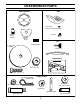
UNASSEMBLED PARTS Steering Wheel Seat (1) Washer 17/32 x 1-3/16 x 12 Gauge Steering Wheel Adapter (1) Knob Steering Wheel Insert Key Steering Sleeve (1) Large Flat Washer (2) Keys (1) Oil Drain Tube Slope Sheet (1) Hex nut 1/2-20 (1) Hex Bolt 1/4-28 x 1-1/4 (4) Retainer Springs (double loop) Gauge Wheels (4) Washers 3/8 x 3/4 x 14 Ga.
ASSEMBLY Your new tractor has been assembled at the factory with exception of those parts left unassembled for shipping purposes. To ensure safe and proper operation of your tractor all parts and hardware you assemble must be tightened securely. Use the correct tools as necessary to insure proper tightness. TOOLS REQUIRED FOR ASSEMBLY A socket wrench set will make assembly easier. Standard wrench sizes are listed.
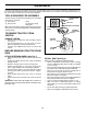
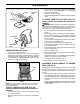
ASSEMBLY • SEAT SHOULDER BOLT • • TO DRIVE TRACTOR OFF SKID (See Operation section for location and function of controls) SEAT PAN WARNING: Before starting, read, understand and follow all instructions in the Operation section of this manual. Be sure tractor is in a well-ventilated area. Be sure the area in front of tractor is clear of other people and objects. • Be sure all the above assembly steps have been completed. • Check engine oil level and fill fuel tank with gasoline.
ASSEMBLY ✓CHECKLIST RETAINER SPRING BEFORE YOU OPERATE YOUR NEW TRACTOR, WE WISH TO ASSURE THAT YOU RECEIVE THE BEST PERFORMANCE AND SATISFACTION FROM THIS QUALITY PRODUCT. PLEASE REVIEW THE FOLLOWING CHECKLIST: ✓ All assembly instructions have been completed. ✓ No remaining loose parts in carton. ✓ Battery is properly prepared and charged. (Minimum 1 hour at 6 amps). ✓ Seat is adjusted comfortably and tightened securely. ✓ All tires are properly inflated.
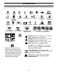
OPERATION These symbols may appear on your tractor or in literature supplied with the product. Learn and understand their meaning.
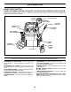
OPERATION KNOW YOUR TRACTOR READ THIS OWNER'S MANUAL AND SAFETY RULES BEFORE OPERATING YOUR TRACTOR Compare the illustrations with your tractor to familiarize yourself with the locations of various controls and adjustments. Save this manual for future reference. ROS "ON" POSITION IGNITION SWITCH ATTACHMENT CLUTCH LEVER LIFT LEVER PLUNGER THROTTLE/CHOKE CONTROL ATTACHMENT LIFT LEVER CLUTCH/BRAKE PEDAL PARKING BRAKE FREE WHEEL CONTROL MOTION CONTROL LEVER LIGHT SWITCH 02853 FIG.
OPERATION The operation of any tractor can result in foreign objects thrown into the eyes, which can result in severe eye damage. Always wear safety glasses or eye shields while operating your tractor or performing any adjustments or repairs. We recommend a wide vision safety mask over spectacles or standard safety glasses. NOTE: Under certain conditions when tractor is standing idle with the engine running, hot engine exhaust gases may cause “browning” of grass.
OPERATION NOTE:Adjust gauge wheels with tractor on a flat level surface. • Adjust mower to desired cutting height (See “TO ADJUST MOWER CUTTING HEIGHT” in the Operation section of this manual). • Remove retainer spring and clevis pin which secure each gauge wheel bar. • Lower gauge wheels to ground. Raise gauge wheels slightly to align holes in bracket and gauge wheel bar and insert clevis pin. Gauge wheels should be slightly off the ground. • Replace retainer spring into clevis pin.
OPERATION Avoid stopping or changing speed on hills. If slowing is necessary, move throttle control lever to slower position. If stopping is absolutely necessary, push clutch/brake pedal quickly to brake position and engage parking brake. Move motion control lever to neutral (N) position. • IMPORTANT: THE MOTION CONTROL LEVER DOES NOT RETURN TO NEUTRAL (N) POSITION WHEN THE CLUTCH/ BRAKE PEDAL IS DEPRESSED.
OPERATION WARM WEATHER STARTING (50° F and above) • When engine starts, move the throttle control to the fast position. • The attachments and ground drive can now be used. If the engine does not accept the load, restart the engine and allow it to warm up for one minute using the choke as described above. COLD WEATHER STARTING ( 50° F and below) • When engine starts, allow engine to run with the throttle control in the choke position until the engine runs roughly, then move throttle control to fast position.
MAINTENANCE MAINTENANCE SCHEDULE FILL IN DATES AS YOU COMPLETE REGULAR SERVICE E E S S RS AG US RS UR OUR OU SON OR U O H O H H A 0 ST E 8H SE RE 25 10 50 Y Y Y Y Y RE O R R R R R O F E E E E E F BE SERVICE EV EV EV EV EV BE H AC DATES Check Brake Operation Check Tire Pressure T R A C T 0 R Check Operator Presence and ROS Systems Check for Loose Fasteners 5 Sharpen/Replace Mower Blades 3 Lubrication Chart Check Battery Level 4 Clean Battery and Terminals Check Transaxle Cooling Check V-Belts Chec
MAINTENANCE TRACTOR BLADE CARE For best results mower blades must be kept sharp. Replace bent or damaged blades. Always observe safety rules when performing any maintenance. BRAKE OPERATION If tractor requires more than five (5) feet to stop at highest speed in highest gear on a level, dry concrete or paved surface, then brake must be checked and adjusted. (See “TO ADJUST BRAKE” in the Ser vice and Adjustments section of this manual).
MAINTENANCE • Slide blade on to an unthreaded portion of the steel bolt or pin and hold the bolt or pin parallel with the ground. If blade is balanced, it should remain in a horizontal position. If either end of the blade moves downward, sharpen the heavy end until the blade is balanced. TRANSAXLE PUMP FLUID The transaxle was sealed at the factory and fluid maintenance is not required for the life of the transaxle.
MAINTENANCE • • • • After oil has drained completely, close and lock the drain valve by pushing inward and turning clockwise until the pin is in the locked position as shown. Remove the drain tube and replace the cap onto to the bottom fitting of the drain valve. Refill engine with oil through oil fill dipstick tube. Pour slowly. Do not overfill. For approximate capacity see “PRODUCT SPECIFICATIONS” section of this manual. Use gauge on oil fill cap/dipstick for checking level.
SERVICE AND ADJUSTMENTS WARNING: TO AVOID SERIOUS INJURY, BEFORE PERFORMING ANY SERVICE OR ADJUSTMENTS: • Depress clutch/brake pedal fully and set parking brake. • Place motion control lever in neutral (N) position. • Place attachment clutch in “DISENGAGED” position. • Turn ignition key to “STOP” and remove key. • Make sure the blades and all moving parts have completely stopped. • Disconnect spark plug wire from spark plug and place wire where it cannot come in contact with plug.
SERVICE AND ADJUSTMENTS SIDE-TO-SIDE ADJUSTMENT (See Figs. 18 and 19) • Raise mower to its highest position. • At the midpoint of both sides of mower, measure height from bottom edge of mower to ground. Distance “A” on both sides of mower should be the same or within 1/4" of each other. • If adjustment is necessary, make adjustment on one side of mower only. • To raise one side of mower, tighten lift link adjustment nut on that side.
SERVICE AND ADJUSTMENTS TO CHECK AND ADJUST BRAKE (See Fig. 23) TO REPLACE MOTION DRIVE BELT (See Fig. 24) Your tractor is equipped with an adjustable brake system which is mounted on the right side of the transaxle. If tractor requires more than five (5) feet to stop at highest speed in highest gear on a level, dry concrete or paved surface, then brake must be checked and adjusted. Park the tractor on level surface. Engage parking brake.
SERVICE AND ADJUSTMENTS • While holding motion control lever in place, loosen the adjustment bolt. • Move motion control lever to the neutral (N) (lock gate) position. • Tighten adjustment bolt securely. NOTE: If additional clearance is needed to get to adjustment bolt, move mower deck height to the lowest position. After above adjustment is made, if the tractor still creeps forward or backward while motion control lever is in neutral position, follow these steps: • Loosen the adjustment bolt.
SERVICE AND ADJUSTMENTS REPLACING BATTERY (See Figs. 28 and 29) TO REPLACE FUSE Replace with 20 amp automotive-type plug-in fuse. The fuse holder is located behind the dash. WARNING: Do not short battery terminals by allowing a wrench or any other object to contact both terminals at the same time. Before connecting battery, remove metal bracelets, wristwatch bands, rings, etc. Positive terminal must be connected first to prevent sparking from accidental grounding.
STORAGE Immediately prepare your tractor for storage at the end of the season or if the tractor will not be used for 30 days or more. ENGINE FUEL SYSTEM IMPORTANT: IT IS IMPORTANT TO PREVENT GUM DEPOSITS FROM FORMING IN ESSENTIAL FUEL SYSTEM PARTS SUCH AS CARBURETOR, FUEL FILTER, FUEL HOSE, OR TANK DURING STORAGE. ALSO, EXPERIENCE INDICATES THAT ALCOHOL BLENDED FUELS (CALLED GASOHOL OR USING ETHANOL OR METHANOL) CAN ATTRACT MOISTURE WHICH LEADS TO SEPARATION AND FORMATION OF ACIDS DURING STORAGE.
TROUBLESHOOTING POINTS PROBLEM Will not start CAUSE 1. 2. 3. 4. 5. 6. 7. Out of fuel. Engine not “CHOKED” properly. Engine flooded. Bad spark plug. Dirty air filter. Dirty fuel filter. Water in fuel. 1. 2. 3. 4. 5. 6. 7. 8. 9. Loose or damaged wiring. Carburetor out of adjustment. 8. 9. 10. Hard to start CORRECTION Engine valves out of adjustment. 10. Fill fuel tank. See “TO START ENGINE” in Operation section. Wait several minutes before attempting to start. Replace spark plug.
TROUBLESHOOTING POINTS PROBLEM CAUSE CORRECTION Engine dies when tractor is shifted into reverse 1. 1. Turn ignition key to ROS "ON" position. See Operation section. Reverse operation system (ROS) is not "ON" while mower or other attachment is engaged. Engine continues to run when operator leaves seat with attachment clutch engaged 1. Faulty operator-safety presence control system. 1. Check wiring, switches and connections. If not corrected, contact an authorized service center/ department.
LIMITED WARRANTY The Manufacturer warrants to the original consumer purchaser that this product as manufactured is free from defects in materials and workmanship. For a period of two (2) years from date of purchase by the original consumer purchaser, we will repair or replace, at our option, without charge for parts or labor incurred in replacing parts, any part which we find to be defective due to materials or workmanship. This Warranty is subject to the following limitations and exclusions. 1.
SERVICE NOTES 28
SUGGESTED GUIDE FOR SIGHTING SLOPES FOR SAFE OPERATION FOL D AL ONG THIS DOT IS A TED 15 D LINE EGR EE S LOP E 29 ONLY RIDE UP AND DOWN HILL, NOT ACROSS HILL 15 DEGREES MAX. WARNING: To avoid serious injury, operate your tractor up and down the face of slopes, never across the face. Do not mow slopes greater than 15 degrees. Make turns gradually to prevent tipping or loss of control. Exercise extreme caution when changing direction on slopes. 1. Fold this page along dotted line indicated above. 2.
PARTS AND SERVICE This product has been expertly engineered and carefully manufactured to rigid quality standards. As with all mechanical products, some adjustments or part replacement may be necessary during the life of your unit. For Parts and service, contact our authorized distributor: call 1-800-849-1297 • For replacement parts, have available the following information: a. Model Number/Manufacturer's I.D. Number b. Description of part.