IMPORTANT MANUAL DO NOT THROW AWAY 03076 OPERATOR'S MANUAL MODEL: PP17538HP WARNING: Read this Manual and follow all Warnings and Safety Instructions. Failure to do so can result in serious injury. LAWN TRACTOR ALWAYS WEAR EYE PROTECTION DURING OPERATION Visit our website: www.poulan-pro.com 420408 Rev.
SAFETY RULES Safe Operation Practices for Ride-On Mowers DANGER: THIS CUTTING MACHINE IS CAPABLE OF AMPUTATING HANDS AND FEET AND THROWING OBJECTS. FAILURE TO OBSERVE THE FOLLOWING SAFETY INSTRUCTIONS COULD RESULT IN SERIOUS INJURY OR DEATH. • WARNING: In order to prevent accidental starting when setting up, transporting, adjusting or making repairs, always disconnect spark plug wire and place wire where it cannot contact spark plug.
SAFETY RULES Safe Operation Practices for Ride-On Mowers III. CHILDREN GENERAL SERVICE • Never operate machine in a closed area. • Keep all nuts and bolts tight to be sure the equipment is in safe working condition. • Never tamper with safety devices. Check their proper operation regularly. • Keep machine free of grass, leaves, or other debris build-up. Clean oil or fuel spillage and remove any fuelsoaked debris. Allow machine to cool before storing.
CUSTOMER RESPONSIBILITIES PRODUCT SPECIFICATIONS Gasoline Capacity and type: 1.50 Gallons Unleaded Regular Oil Type (API-SG-SL): SAE 30 (above 32°F) SAE 5W-30 (below 32°F) Oil Capacity: 48 oz. Spark Plug: Champion RC12YC (Gap: .030") Ground Speed (MPH): Forward: Reverse: Charging System: 3 Amps Battery 5 Amps Headlights Battery: AMP/HR: MIN. CCA: Case Size: Blade Bolt Torque: 45-55 FT. LBS. • • • Read and observe the safety rules.
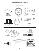
UNASSEMBLED PARTS Steering Wheel Steering Wheel Insert (1) Large Flat Washer Steering Wheel (1) Lock Washer (1) Hex Bolt Steering Wheel Adapter Steering Extension Shaft Steering Boot Seat (1) Washer (1) Seat (1) Bolt Slope Sheet (1) Oil Drain Tube For Future Use Key(s) 5
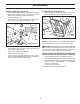
ASSEMBLY Your new tractor has been assembled at the factory with exception of those parts left unassembled for shipping purposes. To ensure safe and proper operation of your tractor all parts and hardware you assemble must be tightened securely. Use the correct tools as necessary to ensure proper tightness. TOOLS REQUIRED FOR ASSEMBLY TO INSTALL STEERING WHEEL (See Fig. 2) A socket wrench set will make assembly easier. Standard wrench sizes are listed.
ASSEMBLY INSTALL SEAT (See Fig. 3 & 4) TO ADJUST SEAT (See Fig. 4) • • • • Remove bolt and flat washer securing seat to cardboard packing and set aside for assembly of seat to tractor. Remove the cardboard packing and discard. Connect switch to seat. Place seat on seat pan so all three (3) bottom pads are positioned over large slotted holes in pan. Grasp adjustment handle and pull up, slide seat to desired position and release adjustment handle.
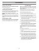
ASSEMBLY ✓CHECKLIST CHECK TIRE PRESSURE The tires on your tractor were overinflated at the factory for shipping purposes. Correct tire pressure is important for best cutting performance. • Reduce tire pressure to PSI shown on tires. BEFORE YOU OPERATE YOUR NEW TRACTOR, WE WISH TO ASSURE THAT YOU RECEIVE THE BEST PERFORMANCE AND SATISFACTION FROM THIS QUALITY PRODUCT.
OPERATION These symbols may appear on your tractor or in literature supplied with the product. Learn and understand their meaning.
OPERATION KNOW YOUR TRACTOR READ THIS OWNER'S MANUAL AND SAFETY RULES BEFORE OPERATING YOUR TRACTOR Compare the illustrations with your tractor to familiarize yourself with the locations of various controls and adjustments. Save this manual for future reference. H D G E B F A K C M L FIG. 5 Our tractors conform to the applicable safety standards of the American National Standards Institute. (F) IGNITION SWITCH - Used for starting and stopping the engine.
OPERATION The operation of any tractor can result in foreign objects thrown into the eyes, which can result in severe eye damage. Always wear safety glasses or eye shields while operating your tractor or performing any adjustments or repairs. We recommend standard safety glasses or a wide vision safety mask worn over spectacles. HOW TO USE YOUR TRACTOR • Turn ignition key (F) to “STOP” position and remove key. Always remove key when leaving tractor to prevent unauthorized use.
OPERATION TO ADJUST MOWER CUTTING HEIGHT (See Fig. 10) The position of the attachment lift lever (A) determines the cutting height. A FIG. 11 TO OPERATE MOWER Your tractor is equipped with an operator presence sensing switch. Any attempt by the operator to leave the seat with the engine running and the attachment clutch engaged will shut off the engine.
OPERATION TO TRANSPORT (See Figs. 5 and 13) WARNING: Backing up with the attachment clutch engaged while mowing is strongly discouraged. Turning the ROS "ON", to allow reverse operation with the attachment clutch engaged, should only be done when the operator decides it is necessary to reposition the machine with the attachment engaged. Do not mow in reverse unless absolutely necessary.
OPERATION ADD GASOLINE • COLD WEATHER STARTING ( 50° F/10° C and below) • When engine starts, allow engine to run with the throttle control in the choke position until the engine runs roughly, then move throttle control to fast position. This may require an engine warm-up period from several seconds to several minutes, depending on the temperature. Fill fuel tank to bottom of filler neck. Do not overfill. Use fresh, clean, regular unleaded gasoline with a minimum of 87 octane.
OPERATION 5. Shut- off engine and set parking brake. 6. Engage transmission by placing freewheel control in engaged position (See “TO TRANSPORT” in this section of manual). 7. Sitting in the tractor seat, start engine. After the engine is running, move throttle control to half (1/2) speed. Disengage parking brake. 8. Drive tractor forward for approximately five feet then backwards for five feet. Repeat this driving procedure three times. Your transmission is now purged and now ready for normal operation.
MAINTENANCE MAINTENANCE SCHEDULE BEFORE EACH USE EVERY 8 HOURS EVERY 25 HOURS EVERY 50 HOURS EVERY 100 HOURS EVERY SEASON BEFORE STORAGE Check Brake Operation T R A C T 0 R Check Tire Pressure Check Operator Presence & ROS Systems Check for Loose Fasteners Check/Replace Mower Blades 3 Lubrication Chart Check Battery Level 4 Clean Battery and Terminals Clean Debris Off Steering Plate Check Transaxle Cooling 5 Check Mower Levelness Check V-Belts Check Engine Oil Level Change Engine Oil (with o
MAINTENANCE TRACTOR BLADE CARE For best results mower blades must be sharp. Replace worn, bent or damaged blades. Always observe safety rules when performing any maintenance. BRAKE OPERATION CAUTION: Use only a replacement blade approved by the manufacturer of your tractor. Using a blade not approved by the manufacturer of your tractor is hazardous, could damage your tractor and void your warranty.
MAINTENANCE TO CHANGE ENGINE OIL (See Fig. 16) TO CLEAN BATTERY AND TERMINALS Corrosion and dirt on the battery and terminals can cause the battery to “leak” power. • Remove terminal guard. • Disconnect BLACK battery cable first then RED battery cable and remove battery from tractor. • Rinse the battery with plain water and dry. • Clean terminals and battery cable ends with wire brush until bright. • Coat terminals with grease or petroleum jelly.
MAINTENANCE ENGINE COOLING SYSTEM (See Fig. 17) CLEANING Debris may clog the engine's air cooling system. Remove blower housing and clean the area shown to prevent overheating and engine damage. • AIR SCREEN • CLEAN OUT CHAFF AND DEBRIS Clean engine, battery, seat, finish, etc. of all foreign matter. Clean debris from steering plate. Debris can restrict clutch/brake pedal shaft movement, causing belt slip and loss of drive. CAUTION: Avoid all pinch points and movable parts (See Fig.
SERVICE AND ADJUSTMENTS WARNING: TO AVOID SERIOUS INJURY, BEFORE PERFORMING ANY SERVICE OR ADJUSTMENTS: • Depress brake pedal fully and set parking brake. • Place attachment clutch in “DISENGAGED” position. • Turn ignition key to “STOP” and remove key. • Make sure the blades and all moving parts have completely stopped. • Disconnect spark plug wire from spark plug and place wire where it cannot come in contact with plug. TO REMOVE MOWER (See Fig.
SERVICE AND ADJUSTMENTS • • ATTACH MOWER SIDE SUSPENSION ARMS (A) TO CHASSIS - Position hole in arm over pin (B) on outside of tractor chassis and secure with retainer spring. Repeat on opposite side of tractor. • Insert end of link (E) into hole in front mower bracket and secure with washer and retainer spring (J). E A J F H B • FIG.
SERVICE AND ADJUSTMENTS TO LEVEL MOWER • If adjustment is necessary, see step in Visual Adjustment instructions above. • Recheck measurements, adjust if necessary until both sides are equal. FRONT-TO-BACK ADJUSTMENT (See Figs. 28 and 29) IMPORTANT: Deck must be level side-to-side. To obtain the best cutting results, the mower blades should be adjusted so the front tip is 1/8" to 1/2" lower than the rear tip when the mower is in its highest position.
SERVICE AND ADJUSTMENTS TO REPLACE MOWER BLADE DRIVE BELT (See Fig. 30) TO REPLACE MOTION DRIVE BELT (See Fig. 31) The mower blade drive belt may be replaced without tools. Park the tractor on level surface. Engage parking brake. Park the tractor on level surface. Engage parking brake. For assistance, there is a belt installation guide decal on bottom side of left footrest. BELT REMOVAL • Remove mower from tractor (See “TO REMOVE MOWER” in this section of manual).
SERVICE AND ADJUSTMENTS FRONT WHEEL TOE-IN/CAMBER TO START ENGINE WITH A WEAK BATTERY (See Fig. 33) Your new tractor front wheel toe-in and camber is set at the factory and is normal. The front wheel toe-in and camber are not adjustable. If damage has occurred to affect the factory set front wheel toe-in or camber, contact a qualified service center. WARNING: Lead-acid batteries generate explosive gases. Keep sparks, flame and smoking materials away from batteries.
SERVICE AND ADJUSTMENTS REPLACING BATTERY (See Fig. 34) TO REPLACE FUSE Replace with 20 amp automotive-type plug-in fuse. The fuse holder is located behind the dash. WARNING: Do not short battery terminals by allowing a wrench or any other object to contact both terminals at the same time. Before connecting battery, remove metal bracelets, wristwatch bands, rings, etc. Positive terminal must be connected first to prevent sparking from ac ci den tal grounding.
STORAGE Immediately prepare your tractor for storage at the end of the season or if the tractor will not be used for 30 days or more. ENGINE FUEL SYSTEM IMPORTANT: IT IS IMPORTANT TO PREVENT GUM DEPOSITS FROM FORMING IN ESSENTIAL FUEL SYSTEM PARTS SUCH AS CARBURETOR, FUEL FILTER, FUEL HOSE, OR TANK DURING STORAGE. ALSO, EXPERIENCE INDICATES THAT ALCOHOL BLENDED FUELS (CALLED GASOHOL OR USING ETHANOL OR METHANOL) CAN ATTRACT MOISTURE WHICH LEADS TO SEPARATION AND FORMATION OF ACIDS DURING STORAGE.
TROUBLESHOOTING POINTS PROBLEM Will not start CAUSE 1. 2. 3. 4. 5. 6. 7. CORRECTION Out of fuel. Engine not “CHOKED” properly. Engine flooded. Bad spark plug. Dirty air filter. Dirty fuel filter. Water in fuel. 1. 2. 3. 4. 5. 6. 7. Fill fuel tank. See “TO START ENGINE” in Operation section. Wait several minutes before attempting to start. Replace spark plug. Clean/replace air filter. Replace fuel filter. Empty fuel tank and carburetor, refill tank with fresh gasoline and replace fuel filter. 8.
TROUBLESHOOTING POINTS PROBLEM CAUSE CORRECTION Engine continues to run when operator leaves seat with attachment clutch engaged 1. Faulty operator-safety presence control system. 1. Check wiring, switches and connections. If not corrected, contact an authorized service center/ department. Poor cut - uneven 1. 2. 3. 4. 5. Worn, bent or loose blade. Mower deck not level. Buildup of grass, leaves, trash under mower. Bent blade mandrel.
SUGGESTED GUIDE FOR SIGHTING SLOPES FOR SAFE OPERATION FOL DA L O NG D THIS O I T S T A E D LIN 1 5 DEG E RE E S LOP E ONLY RIDE UP AND DOWN HILL, NOT ACROSS HILL 15 DEGREES MAX. WARNING: To avoid serious injury, operate your tractor up and down the face of slopes, never across the face. Do not mow slopes greater than 15 degrees. Make turns gradually to prevent tipping or loss of control. Exercise extreme caution when changing direction on slopes. 1. Fold this page along dotted line indicated above. 2.
SERVICE NOTES 30
SERVICE NOTES 31
10.29.09 SR Printed in the U.S.A.