
Manual

dDbWAI-iI_III_IL_,Ifreceivedassembled,
repeataltstepstoensureyourunitisproperly
assembledandallfastenersaresecure.
Examh_epartsfordamage.Donotusedam-
agedparts.
NOTE:Ifyouneedassistanceorfindparts
missingordamaged,call1-800-554-6723.
Itisnormalforthefuelfiltertorattleinthe
emptyfueltank.
Fh_dingfueloroilresidueonmufflerisnormal
duetocarburetoradjustmentsandtesting
donebythemanufacturer.
TOOLSREQUIRED
• Hexwrench(provided)
INSTALLINGPRUNERATTACH-
MENT
CAUTION:Whenremovingorinstallingat-
tachments,placetheunitonaflatsurfacefor
stability.
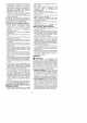
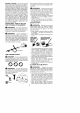
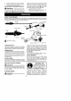
1. Loosenthecouplerbyturningtheknob
counterclockwise.
Coupler
Shipping
protector
Knob
TIGHTEN
2. Removeshippingprotectorfromcoupler.
3. Removetheshaftcapfromtheprunerat-
tachment(ifpresent).
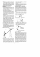
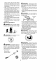
4. Positionlocking/releasebuttonofattach-
mentintoguiderecessofcoupler.
5. Pushtheattachmentintothecoupleruntil
thelocking/releasebuttonsnapsintothe
primaryhole.
6. Beforeusingtheunit.tightentheknobse-
curelybyturningclockwise.
CouplerPrimaryHole
GuideRecess
SecondaryHole
Locking/Release
ButtoninPrimaryHole
Foroptionalattachments,seetheAS-
SEMBLYsectionoftheapplicableattach-
mentinstructionmanual.
SHOULDER STRAP ASSEMBLY
_L, WARNING: Proper shoulder strap
adjustments must be made with the engine
completely stopped before using unit.
1. Try on shoulder strap and adjust for fit
and balance before starting the engine or
beginning a cutting operation.
2. Insert your right arm and head through
the shoulder strap and allow it to rest on
your left shoulder. Make sure the danger
sign is centered on your back and the
hook is to the right side of your waist.
NOTE: A one-half twist is built in the shoul-
der strap to allow the strap to rest flat on the
shoulder.
3. Adjust the strap, allowing the hook to be
about 3 - 6 inches (8 - 15 cm) below the
waist.
4. Fasten the strap hook to the clamp io-
cated between the throttle handte and the
assist handle and lift the tool to the oper-
ating position.
NOTE: It may be necessary to relocate the
shoulder strap clamp on the shaft for proper
balancing of unit.
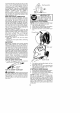
TO RELOCATE SHOULDER STRAP
CLAMP:
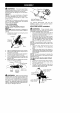
1. Loosen and remove both clamp screws.
2. Place the upper shoulder strap clamp
over the upper shaft.
3. Position the lower shoulder strap clamp
under the upper shaft and align the upper
and lower clamp screw holes.
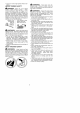
Upper Locking/ Attachment
Shaft Release
Button
,&
rmWARNING: Make sure the tocking/
retease button is locked in the primary hole
and the knob is securely tightened before op-
erating the unit. All attachments are designed
to be used in the primary hoIe unless otherwise
stated in the applicable attachment instruction
manual. Using the wrong hole could lead to seri-
ous injury or damage to the unit.
POWERHEAD
END
Upper Shoulder
Clamp
db
Lower Shoulder | Aqq-ACHMENT
Strap Clamp _ END
Screws