
Manual

_ItWARNING: Ifreceivedassembled,
repeat all steps to ensure your unit is properly
assembled and alI fasteners are secure.
Examine parts for damage. Do not use dam-
aged parts
NOTE: if you need assistance or find parts
missing or damaged, call 1-800-554-6723.
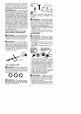
It is normaI for the fuel fiIter to rattle in the
empty fuel tank.
Finding fuel or oil residue on muffler is normal
due to carburetor adjustments and testing
done by the manufacturer
TOOLS REQUIRED
• Hex wrench (provided)
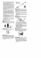
INSTALLING PRUNER ATTACH-
MENT
CAUTION: When removing or installing at-
tachments, p}ace the unit on a fiat surface for
stability.
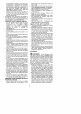
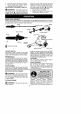
1. Loosen the coupler by turning the knob
counterclockwise.
Coupler
Shipping
protector
Knob
TIGHTEN
2. Remove shipping protector from coupler.
3. Remove the shaft cap from the pruner at-
tachment (if present).
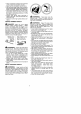
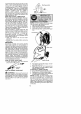
4. Position locking/release button of attach-
ment into guide recess of coupler
5. Push the attachment into the coupler until
the locking!release button snaps intothe
primary hole.
6. Before using the unit, tighten tbe knob se-
curely by turning clockwise
Couple r Primary Hole
Secondary Hole
Locking/Release
Button in Primary Hole
For optional attachments, see the AS-
SEMBLY section of the applicable attach-
ment instruction manual
SHOULDER STRAP ASSEMBLY
E21,W,_IdNII_Ir_: Proper shoulder strap
adjustments must be made with the engine
completely stopped before using unit
1. Try on shoulder strap and adjust for fit
and batance before starting the engine or
beginning a cutting operation
2. Insert your right arm and head through
the shoulder strap and allow it to rest on
your left shoulder. Make sure the danger
sign is centered on your back and the
hook is to the right side of your waist.
NOTE: A one-half twist is built in the shoul-
der strap to a_low the strap to rest flat on the
shoulder.
3. Adjust the strap, allowing the hook to be
about 3 - 6 inches (8 - t5 cm) betow the
waist.
4. Fasten the strap hook to the clamp lo-
cated between the throttle handle and the
assist handle and lift the too] to the oper-
ating position
NOTE: It may be necessary to relocate the
sbeu_der strap clamp on the shaft for proper
balancing of unit.
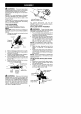
TO RELOCATE SHOULDER STRAP
CLAMP:
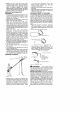
1. Loosen and remove both clamp screws.
2. Place the upper shoulder strap clamp
over the upper shaft.
3. Position the lower shoulder strap clamp
under the upper shaft and align the upper
and _ower clamp screw holes
Upper Locking/ Attachment
Shaft Re}ease
Button
_I=WARNING: Make sure the locking/
release button is locked in the primary hole
and the knob is securely tightened before op-
erating the unit. All attachments are designed
to be used in the primary hole unless otherwise
stated in the applicable attachment instruc_en
manuat. Using the wrong hole could lead to seri-
ous injury or damage to the unit.
POWERHEAD
END
Strap Clamp
Lower Shoulder | A_ACHMENT
Strap C_amp _l END
_crews