Model: PP4300/PP6600/PP6600E/PP7600E IMPORTANT - Please make certain the person who uses this generator thoroughly reads these instructions and all other instructions provided to ensure proper safety, use, and care of your new portable electric generator. Consumers service: 1-800-849-1297 WWW.POULANPRO.
TABLE OF CONTENTS INTRODUCTION .................................................................................................2 SAFETY RULES ............................................................................................. 3-4 SYMBOLS....................................................................................................... 5-7 FEATURES ................................................................................................... 8-10 ASSEMBLY .................................
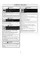
SAFETY RULES DANGER WARNING Running generator gives off carbon monoxide, an odorless, colorless, poison gas. Breathing carbon monoxide will cause nausea, fainting, or death. Fuel and its vapors are extremely flammable and explosive. Fire or explosion can cause severe burns or death. ● Operate generator ONLY outdoors. ● Keep clearance on all sides of generator for adequate ventilation. WHEN ADDING FUEL: ● Turn generator OFF and let it cool at least 2 minutes before removing gas cap.
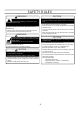
SAFETY RULES CAUTION WARNING Exceeding generator’s wattage/amperage capacity can damage generator and/or electrical devices connected to it. Unintentional sparking can result in fire or electric shock. ● See “Don’t Overload Generator” on page 17. ● Start generator and let engine stabilize before connecting electrical loads. ● Connect electrical loads in OFF position, then turn ON for operation. ● Turn electrical loads OFF and disconnect from generator before stopping generator.
SYMBOLS Some of the following symbols may be used on this generator. Please study them and learn their meaning. Proper interpretation of these symbols will allow you to operate the generator better and safer.
SYMBOLS The following signal words and meanings are intended to explain the levels of risk associated with this product.
SYMBOLS SAFETY LABELS The following labels are found on the generator. For your safety, please study and understand all of the labels before starting the generator. If any of the labels come off the unit or become hard to read, contact an authorized service center for replacement. FUEL WARNING DO NOT SMOKE when filling with gasoline. Do not over fill. Full level is 1 inch below the top of the fuel neck. Stop the engine two minutes before refueling to avoid the heat from the muffler igniting fuel vapors.
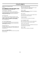
FEATURES SPECIFICATIONS GENERATOR PP4300 PP6600 PP6600E PP7600E 60 Hz 60 Hz 60 Hz 60 Hz AC OUTPUT: Frequency (Hertz) Voltage Rated Power 120 / 240 Volts 120 / 240 Volts 120 / 240 Volts 120 / 240 Volts 4300 Watts 6600 Watts 6600 Watts 7600 Watts ENGINE Engine Type Engine Speed (RPM) Single Cylinder, Forced Air Cooling, 4-Stroke 3600 3600 3600 3600 Gasoline Gasoline Gasoline Gasoline 1L 1L 1L 1L Spark Plug Type F7TC F7TC F7TC F7TC Spark Plug Gap 0.7 mm 0.7 mm 0.7 mm 0.
FEATURES FUEL LEVEL GAUGE FUEL TANK CAP FUEL TANK AC CIRCUIT BREAKER 120 VOLTS AC RECEPTACLES CHOKE LEVER ENGINE SWITCH AIR FILTER 120/240 VOLTS AC RECEPTACLES FUEL VALVE RECOIL STARTER GRIP BATTRAY (IF EQUIPPED) WHEEL HANDLE GROUNDING TERMINAL OIL FILL CAP/DIPSTICK OIL DRAINAGE BOLTS FOOT Fig.
FEATURES KNOW YOUR GENERATOR RECOIL STARTER GRIP See Fig. 1 The recoil starter grip is used (along with the engine switch) to start the generator抯 engine. with all operating features and safety rules. FUEL VALVE GROUNDING TERMINAL The flow of fuel through the generator is controlled by the position of the fuel valve. The grounding terminal is used to assist in properly grounding the generator to help protect against electrical shock.
ASSEMBLY UNASSEMBLED PARTS The following assembly hardware items are included with the generator. See Fig. 2 Wheel Assembly ..............................................................1 Handle Assembly.............................................................1 Foot Assembly.................................................................1 Fig.
ASSEMBLY INSTRUCTIONS INSTALLING HANDLE ASSEMBLY This product requires assembly. See Fig. 3 Carefully remove the generator and any accessories from the box. NOTE: The generator is heavy. To avoid back injury, lift with your legs, not your back, and get help when needed. ■ ■ Handle Left and right handle brackets 4 bolts 4 nuts Assemble the bracket on the frame with bolts and nuts Make sure that all items listed in the unassembled parts list are included. breakage or damage occurred during shipping.
ASSEMBLY INSTALLING WHEEL ASSEMBLY 2 wheels 2 flat washers 2 pins 4 bolts 4 nuts ■ Slide wheel over axle extension. ■ Slide flat washer on axle extension. ■ Install hex nut on axle extension and tighten to secure. Repeat for second wheel. NOTE: Block up frame securely with wood blocks to provide clearance for frame bolts & wheel assembly. ■ ■ Slide square curved washer, curved side down, on bolt. ■ Place on frame and slide bolt through frame hole. ■ Repeat for second bolt.
OPERATION GROUNDING THE GENERATOR The National Electrical Code requires that the frame and external electrically conductive parts of this generator be properly connected to an approved earth ground. Local electrical codes may also require proper grounding of the unit. For that purpose, a GROUNDING FASTENER is provided on the generator end (Figure 6). Grounding fastener Fig. 6 Generally, connecting a No.
OPERATION DANGER: Failure to properly ground generator can result in electrocution, especiallyif the generator is equipped with a wheel kit. National Electric Code requires generator to be properly grounded to an approved earth ground. Call an electrician for local grounding requirements OIL DIPSTICK WARNING: Do not use any attachments or accessories not recommended by the manufacturer of this generator. The use of attachments or accessories not recommended can result in serious personal injury.
OPERATION If using an oxygenated fuel, make sure it is unleaded and meets the minimum octane rating requirements. Before using an oxygenated fuel, try to confirm the fuel抯 contents. Some states/provinces require this information to be posted on the pump. The following are the EPA approved percentages of oxygenates: Ethanol (ethyl or grain alcohol) 10% by volume. You may use gasoline containing up to 10% ethanol by volume. Gasoline containing ethanol may be marketed under the name “Gasohol”.
ELECTRICAL DON'T OVERLOAD GENERATOR WARNING: CAPACITY Do not overload generator's capacity. Exceeding generator's wattage/amperage capacity can damage generator and/or electrical devices connected to it. Make sure the generator can supply enough rated (running) and surge (starting) watts for the items you will power at the same time. Follow these simple steps: 1. Select the items you will power at the same time. 2. Total the rated (running) watts of these items.
MAINTENANCE WARNING: When servicing, use only identical Poulan Pro replacement parts. Use of any other parts may create a hazard or cause product damage. Only the parts shown on the parts list are intended to be repaired or replaced by the customer. All other parts should be replaced at a Poulan Pro Authorized Service Center. GENERAL MAINTENANCE Keep the generator in a clean and dry environment where it is not exposed to dust, dirt, moisture, or corrosive vapors.
MAINTENANCE CLEANING FUEL SEDIMENT CUP gotten into the fuel tank from entering the carburetor. If the engine has not been run for a long time, the sediment cup should be cleaned before use. ■ ■ ■ ■ ■ ■ Turn the fuel valve to the off position. Remove the sediment cup using a 10 mm wrench. Remove the o-ring and filter. Clean each of the parts in a high flash-point solvent. Reinstall the filter, o-ring, and sediment cup. Tighten with 10 mm wrench to secure.
MAINTENANCE MAINTENANCE SCHEDULE S E R V IC E IT E M S 3 EVERY 6 EVERY F IR S T USE MONTH OR M O NTHS O R M O NTHS O R YEAR O R 20 H O U R S 50 H O U R S 100 H O U R S 300 H O U R S G e n e ra l In s p e c tio n X1 C h e c k O il L e v e l X C h a n g e E n g in e O il EVERY E ACH X X C le a n A ir C le a n e r X 2 C le a n C ylin d e r C o o lin g F in s X 2 C le a n S p a rk P lu g X C le a n th e S p a rk A rre s to r X 3 C le a n F u e l S e d im e n t C u p X C le a
TROUBLESHOOTING PROBLEM POSSIBLE CAUSE SOLUTION Engine will not start Engine switch is OFF Turn engine switch to ON. No fuel Fill fuel tank. Oil level is low Check engine oil level and fill, if necessary Check spark plug condition Replace spark plug. Fuel is not reaching carburetor Clean fuel sediment cup.
WARRANTY 1. FEDERALEMISSION CONTROLWARRANTYSTATEMENT YOUR WARRANTY RIGHTS AND OBLIGATIONS The United States Environmental Protection Agency(EPA), together with Husqvarna Consumer Outdoor Products NA, Inc., are pleased to explain the emission control system warranty on your new model year small off-road engines. In the United States (except California), new small off-road engines must be designed, built and equipped to meet the Federal’s stringent anti-smog standards.
WARRANTY II. EMISSION CONTROL SYSTEM WARRANTY Emission Control System Warranty (ECS Warranty) for 2009 and later model engines: (a) Applicability: This warranty shall apply to 2009 and later model year engines. The ECS Warranty Period shall begin on the date the new engine or equipment is purchased by/delivered to its original, end-use purchaser/owner and shall continue for 24 consecutive months thereafter. (b) General Emissions Warranty Coverage: Husqvarna Consumer Outdoor Products NA, Inc.
WARRANTY Husqvarna Consumer Outdoor Products NA, Inc. engine. Such use voids this ECS Warranty and shall be sufficient grounds for disallowing an ECS Warranty claim. Husqvarna Consumer Outdoor Products NA, Inc. shall not be held liable hereunder for failures of any warranted parts of a Husqvarna Consumer Outdoor Products NA, Inc. engine caused by the use of such an unapproved, add-on, modified, counterfeit and/or "grey market" part.
WARRANTY EMISSIONS MAINTENANCE SCHEDULE AND WARRANTED PARTS LIST Emissions Parts Inspect Before Each Use Clean Every 5 Hours Replace Every 25 Hours or Yearly Clean Every 25 Hours or Yearly AIR FILTER ASSY INCLUDES: FILTER...................................................................................X.....................................X SPARK SCREEN.............................................................................................................................................
LIMITED WARRANTY HOP (The "Manufacturer") warrants to the original consumer purchaser that this product as manufactured is free from defects in materials and workmanship. For a period of two (2) years from date of purchase by the original consumer purchaser, we will repair or replace, at our option, without charge for parts or labor incurred in replacing parts, any part which we find to be defective due to materials or workmanship. This Warranty is subject to the following limitations and exclusions. 1.
SERVICE NOTES 27
● SERVICE Now that you have purchased your tool, should a need ever exist for repair parts or service, simply contact your nearest Poulan Pro Authorized Service Center. Be sure to provide all pertinent facts when you call or visit. Please call 1-800-849-1297 for your nearest Poulan Pro Authorized Service Center. You can also check our web site at www.poulanpro.com for a complete list of Authorized Service Centers. ● MODEL NO. AND SERIAL NO.