IMPORTANT MANUAL Do Not Throw Away 02478 OWNER'S MANUAL MODEL: PR185H42STH WARNING: Read this Owner's Manual and follow all Warnings and Safety Instructions. Failure to do so can result in serious injury. LAWN TRACTOR ALWAYS WEAR EYE PROTECTION DURING OPERATION 183371 03.13.02 RH Printed in U.S.A.
SAFETY RULES Safe Operation Practices for Ride-On Mowers IMPORTANT: THIS CUTTING MACHINE IS CAPABLE OF AMPUTATING HANDS AND FEET AND THROWING OBJECTS. FAILURE TO OBSERVE THE FOLLOWING SAFETY INSTRUCTIONS COULD RESULT IN SERIOUS INJURY OR DEATH. I. GENERAL OPERATION • • • • • • • • • • • • • • • • • • Avoid starting or stopping on a slope. If tires lose traction, disengage the blades and proceed slowly straight down the slope.
SAFETY RULES Safe Operation Practices for Ride-On Mowers • • • • • • • • • • • • • • Look for this symbol to point out important safety precautions. It means CAUTION!!! BECOME ALERT!!! YOUR SAFETY IS INVOLVED. Be sure the area is clear of other people before mowing. Stop machine if anyone enters the area. Never carry passengers or children even with the blades off. Do not mow in reverse unless absolutely necessary. Always look down and behind before and while backing. Never carry children.
CONGRATULATIONS on your purchase of a new Tractor. It has been designed, engineered and manufactured to give you the best possible dependability and performance. Should you experience any problem you cannot easily remedy, please contact your nearest authorized service center. We have competent, well-trained technicians and the proper tools to service or repair this tractor. Please read and retain this manual. The instructions will enable you to assemble and maintain your tractor properly.
UNASSEMBLED PARTS Seat Steering Wheel Steering Wheel Insert (1) Washer 17/32 x 1-3/16 x 12 Gauge (1) Knob Steering Extension Shaft Steering Sleeve Slope Sheet Steering Adapter (1) Large Flat Washer (1) Oil Drain Tube (1) Locknut 1/2-20 (2) Keys (2) Mulch Blades (1) Hex Bolt 1/4-28 x 1-1/4 (1) Locknut 1/4-28 5
ASSEMBLY Your new tractor has been assembled at the factory with exception of those parts left unassembled for shipping purposes. To ensure safe and proper operation of your tractor all parts and hardware you assemble must be tightened securely. Use the correct tools as necessary to insure proper tightness. TOOLS REQUIRED FOR ASSEMBLY INSERT A socket wrench set will make assembly easier. Standard wrench sizes are listed.
ASSEMBLY NOTE: You may now roll or drive your tractor off the skid. Follow the appropriate instruction below to remove the tractor from the skid. SEAT PAN TO ROLL TRACTOR OFF SKID (See Operation section, page 10, for location and function of controls) LABEL • • • FIG. 2 • • INSTALL SEAT (See Fig. 3) Adjust seat before tightening adjustment knob. • Remove adjustment knob and flat washer securing seat to cardboard packing and set aside for assembly of seat to tractor.
ASSEMBLY CHECK DECK LEVELNESS IMPORTANT: FOR SHIPPING PURPOSES, THE MULCHER PLATE WAS PREATTACHED TO YOUR MOWER. THE MULCHER PLATE MUST ONLY BE USED WITH THE MULCHING BLADES THAT CAME PACKED SEPARATELY IN THE CARTON. For best cutting results, mower housing should be properly leveled. See “TO LEVEL MOWER HOUSING” in the Service and Adjustments section of this manual.
OPERATION These symbols may appear on your tractor or in literature supplied with the product. Learn and understand their meaning.
OPERATION KNOW YOUR TRACTOR READ THIS OWNER'S MANUAL AND SAFETY RULES BEFORE OPERATING YOUR TRACTOR Compare the illustrations with your tractor to familiarize yourself with the locations of various controls and adjustments. Save this manual for future reference.
OPERATION The operation of any tractor can result in foreign objects thrown into the eyes, which can result in severe eye damage. Always wear safety glasses or eye shields while operating your tractor or performing any adjustments or repairs. We recommend a wide vision safety mask over spectacles or standard safety glasses. HOW TO USE YOUR TRACTOR • TO SET PARKING BRAKE (See Fig. 6) IMPORTANT: LEAVING THE IGNITION SWITCH IN ANY POSITION OTHER THAN "OFF" WILL CAUSE THE BATTERY TO BE DISCHARGED, (DEAD).
OPERATION • For best cutting performance, grass over 6 inches in height should be mowed twice. Make the first cut relatively high; the second to desired height. "ENGAGED" POSITION ATTACHMENT LIFT LEVER HIGH POSITION TO ADJUST GAUGE WHEELS (See Fig. 7) ATTACHMENT CLUTCH LEVER "DISENGAGED" POSITION Gauge wheels are properly adjusted when they are slightly off the ground when mower is at the desired cutting height in operating position.
OPERATION CAUTION: Alcohol blended fuels (called gasohol or using ethanol or methanol) can attract moisture which leads to separation and formation of acids during storage. Acidic gas can damage the fuel system of an engine while in storage. To avoid engine problems, the fuel system should be emptied before storage of 30 days or longer. Drain the gas tank, start the engine and let it run until the fuel lines and carburetor are empty. Use fresh fuel next season.
OPERATION AUTOMATIC TRANSMISSION WARM UP • Before driving the unit in cold weather, the transmission should be warmed up as follows: • Be sure the tractor is on level ground. • Place the motion control lever in neutral. Release the parking brake and let the clutch/brake s l o w l y return to operating position. • Allow one minute for transmission to warm up. This can be done during the engine warm up period.
OPERATION MULCHING MOWING TIPS MAX 1/3 IMPORTANT: FOR BEST PERFORMANCE, KEEP MOWER HOUSING FREE OF BUILT-UP GRASS AND TRASH. CLEAN AFTER EACH USE. • • • • • The special mulching blade will recut the grass clippings many times and reduce them in size so that as they fall onto the lawn they will disperse into the grass and not be noticed. Also, the mulched grass will biodegrade quickly to provide nutrients for the lawn.
CUSTOMER RESPONSIBILITIES MAINTENANCE SCHEDULE FILL IN DATES AS YOU COMPLETE REGULAR SERVICE E E S S RS AG US RS UR OUR OU SON OR H U O H C T O H H A 0 S EA 8H SE RE 25 50 10 Y Y Y Y Y RE O R R R R R O F E E E E E F BE SERVICE EV EV EV EV EV BE DATES Check Brake Operation Check Tire Pressure T R A C T 0 R Check Operator Presence and Interlock Systems Check for Loose Fasteners 5 Sharpen/Replace Mower Blades 3 Lubrication Chart Check Battery Level 4 Clean Battery and Terminals Check Transaxle Cooli
CUSTOMER RESPONSIBILITIES TRACTOR MANDREL ASSEMBLY TRAILING EDGE UP BLADE Always observe safety rules when performing any maintenance. CENTER HOLE BRAKE OPERATION If tractor requires more than six (6) feet stopping distance at high speed in highest gear, then brake must be adjusted. (See “TO ADJUST BRAKE” in the Service and Adjustments section of this manual). LOCK WASHER STAR TIRES • Maintain proper air pressure in all tires (See “PRODUCT SPECIFICATIONS” section of this manual).
CUSTOMER RESPONSIBILITIES BATTERY SAE VISCOSITY GRADES Your tractor has a battery charging system which is sufficient for normal use. However, periodic charging of the battery with an automotive charger will extend its life. • Keep battery and terminals clean. • Keep battery bolts tight. • Keep small vent holes open. • Recharge at 6-10 amperes for 1 hour. NOTE: The original equipment battery on your tractor is maintenance free. Do not attempt to open or remove caps or covers.
CUSTOMER RESPONSIBILITIES CLEAN AIR SCREEN ENGINE OIL FILTER Air screen must be kept free of dirt and chaff to prevent engine damage from overheating. Clean with a wire brush or compressed air to remove dirt and stubborn dried gum fibers. Replace the engine oil filter every season or every other oil change if the tractor is used more than 100 hours in one year.
SERVICE AND ADJUSTMENTS WARNING: TO AVIOD SERIOUS INJURY, BEFORE PERFORMING ANY SERVICE OR ADJUSTMENTS: • Depress clutch/brake pedal fully and set parking brake. • Place motion control lever in neutral (N) position. • Place attachment clutch in “DISENGAGED” position. • Turn ignition key to “STOP” and remove key. • Make sure the blades and all moving parts have completely stopped. • Disconnect spark plug wire from spark plug and place wire where it cannot come in contact with plug.
SERVICE AND ADJUSTMENTS TO LEVEL MOWER HOUSING • Adjust the mower while tractor is parked on level ground or driveway. Make sure tires are properly inflated (See “PRODUCT SPECIFICATIONS” section of this manual). If tires are over or underinflated, you will not properly adjust your mower. • • • SIDE-TO-SIDE ADJUSTMENT (See Figs. 19 and 20) • Raise mower to its highest position. • At the midpoint of both sides of mower, measure height from bottom edge of mower to ground.
SERVICE AND ADJUSTMENTS TO REPLACE MOWER BLADE DRIVE BELT (See Fig. 23) TO REPLACE MOTION DRIVE BELT (See Fig. 25) The mower blade drive belt may be replaced without tools. Park the tractor on level surface. Engage parking brake. BELT REMOVAL • Remove mower from tractor (See “TO REMOVE MOWER” in this section of manual). • Work belt off both mandrel pulleys and idler pulleys. • Pull belt away from mower. BELT INSTALLATION • Work belt around both mandrel pulleys and idler pulleys.
SERVICE AND ADJUSTMENTS TRANSMISSION REMOVAL/REPLACEMENT TO ADJUST STEERING WHEEL ALIGNMENT Should your transmission require removal for service or replacement, it should be purged after reinstallation and before operating the tractor. See “PURGE TRANSMISSION” in the Operation section of this manual. If steering wheel crossbars are not horizontal (left to right) when wheels are positioned straight forward, remove steering wheel and reassemble per instructions in the Assembly section of this manual.
SERVICE AND ADJUSTMENTS TO START ENGINE WITH A WEAK BATTERY (See Fig. 28) REPLACING BATTERY (See Figs. 29 and 30) CAUTION: Do not short battery terminals by allowing a wrench or any other object to contact both terminals at the same time. Before connecting battery, remove metal bracelets, wristwatch bands, rings, etc. Positive terminal must be connected first to prevent sparking from accidental grounding. WARNING: Lead-acid batteries generate explosive gases.
SERVICE AND ADJUSTMENTS INTERLOCKS AND RELAYS • Loose or damaged wiring may cause your tractor to run poorly, stop running, or prevent it from starting. • Check wiring. See electrical wiring diagram in the Repair Parts section. • TO ADJUST CARBURETOR Your carburetor is not adjustable. If your engine does not operate properly due to suspected carburetor problems, take your tractor to an authorized service center for repair and/or adjustment. High speed stop is factory adjusted.
STORAGE ENGINE Immediately prepare your tractor for storage at the end of the season or if the tractor will not be used for 30 days or more. FUEL SYSTEM CAUTION: Never store the tractor with gasoline in the tank inside a building where fumes may reach an open flame or spark. Allow the engine to cool before storing in any enclosure. IMPORTANT: IT IS IMPORTANT TO PREVENT GUM DEPOSITS FROM FORMING IN ESSENTIAL FUEL SYSTEM PARTS SUCH AS CARBURETOR, FUEL FILTER, FUEL HOSE, OR TANK DURING STORAGE.
TROUBLESHOOTING POINTS PROBLEM Will not start CAUSE 1. 2. 3. 4. 5. 6. 7. Out of fuel. Engine not “CHOKED” properly. Engine flooded. Bad spark plug. Dirty air filter. Dirty fuel filter. Water in fuel. 1. 2. 3. 4. 5. 6. 7. 8. 9. Loose or damaged wiring. Carburetor out of adjustment. 8. 9. 10. Hard to start CORRECTION Engine valves out of adjustment. 10. Fill fuel tank. See “TO START ENGINE” in Operation section. Wait several minutes before attempting to start. Replace spark plug.
TROUBLESHOOTING POINTS PROBLEM CAUSE CORRECTION Engine continues to run 1. when operator leaves seat with attachment clutch engaged Faulty operator-safety presence control system. 1. Check wiring, switches and connections. If not corrected, contact an authorized service center/ department. Poor cut - uneven 1. 2. 3. 4. 5. Worn, bent or loose blade. Mower deck not level. Buildup of grass, leaves, and trash under mower. Bent blade mandrel.
TRACTOR - - MODEL NUMBER PR185H42STH PRODUCT NO.
TRACTOR - - MODEL NUMBER PR185H42STH PRODUCT NO. 954 56 67-82 ELECTRICAL 22 21 42 24 41 43 27 27 40 26 27 27 25 16 16 33 30 52 D.C .
TRACTOR - - MODEL NUMBER PR185H42STH PRODUCT NO. 954 56 67-82 ELECTRICAL KEY NO. 1 2 8 16 21 22 24 25 26 27 28 29 30 33 40 41 42 43 45 52 90 PART NO.
TRACTOR - - MODEL NUMBER PR185H42STH PRODUCT NO.
TRACTOR - - MODEL NUMBER PR185H42STH PRODUCT NO. 954 56 67-82 CHASSIS KEY NO. PART NO.
TRACTOR - - MODEL NUMBER PR185H42STH PRODUCT NO.
TRACTOR - - MODEL NUMBER PR185H42STH PRODUCT NO. 954 56 67-82 DRIVE KEY NO. PART NO.
TRACTOR - - MODEL NUMBER PR185H42STH PRODUCT NO.
TRACTOR - - MODEL NUMBER PR185H42STH PRODUCT NO. 954 56 67-82 STEERING ASSEMBLY KEY NO. PART NO.
TRACTOR - - MODEL NUMBER PR185H42STH PRODUCT NO. 954 56 67-82 SEAT ASSEMBLY 1 8 8 9 14 9 7 7 10 5 6 22 21 2 24 5 16 25 15 11 4 13 17 KEY NO. 1 2 3 4 5 6 7 8 9 10 11 12 PART NO. 171683 140551 71110616 19131610 145006 73800600 124181X 17000616 19131614 182493 166369 121246X 3 12 DESCRIPTION Seat Bracket Pivot Seat 8 720 Bolt Fin Hex 3/8-16unc X 1 Washer 13/32 X 1 X 10 Ga Clip Push-In Nut Hex w/Ins. 3/8-16 Unc Spring Seat Cprsn 2 250 Blk Zi Screw 3/8-16 x 1.5 Smgml Washer 13/32 X 1 X 14 Ga.
TRACTOR - - MODEL NUMBER PR185H42STH PRODUCT NO. 954 56 67-82 DECALS 2 7 11 16 4 4 3 10 2 20 9 1 8 6 12 5 14 KEY NO. 1 2 3 4 5 6 7 8 9 10 11 PART NO. 157032 176303 176308 176309 174410 170563 180892 179128 172740 157140 172743 13 KEY NO.
TRACTOR - - MODEL NUMBER PR185H42STH PRODUCT NO.
TRACTOR - - MODEL NUMBER PR185H42STH PRODUCT NO. 954 56 67-82 ENGINE KEY NO. PART NO.
TRACTOR - - MODEL NUMBER PR185H42STH PRODUCT NO.
TRACTOR - - MODEL NUMBER PR185H42STH PRODUCT NO. 954 56 67-82 MOWER DECK KEY NO. 1 2 3 4 5 6 8 9 10 11 13 14 15 16 18 19 20 21 23 24 25 26 27 28 29 30 31 32 33 34 36 37 40 44 45 46 48 49 50 51 52 53 54 55 56 59 67 68 PART NO. DESCRIPTION 165892X421 Mower Deck Assembly, 42" 72140506 Bolt 138017 Bracket Asm Fr.
TRACTOR - - MODEL NUMBER PR185H42STH PRODUCT NO.
TRACTOR - - MODEL NUMBER PR185H42STH PRODUCT NO. 954 56 67-82 MOWER LIFT KEY NO. PART NO.
LIMITED WARRANTY The Manufacturer warrants to the original consumer purchaser that this product as manufactured is free from defects in materials and workmanship. For a period of two (2) years from date of purchase by the original consumer purchaser, we will repair or replace, at our option, without charge for parts or labor incurred in replacing parts, any part which we find to be defective due to materials or workmanship. This Warranty is subject to the following limitations and exclusions. 1.
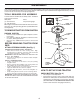
1. Fold this page along dotted line indicated above. 2. Hold page before you so that its left edge is vertically parallel to a tree trunk or other upright structure. 3. Sight across the fold in the direction of hill slope you want to measure. 4. Compare the angle of the fold with the slope of the hill. WARNING: To avoid serious injury, operate your tractor up and down the face of slopes, never across the face. Do not mow slopes greater than 15 degrees.
PARTS AND SERVICE Your POULAN PRO product has been expertly engineered and carefully manufactured to rigid quality standards. As with all mechanical products, some adjustments or part replacement may be necessary during the life of your unit. FOR SERVICE OR REPLACEMENT PARTS: 1. Consult your dealer/place of purchase. 2. Consult the yellow pages of your phone directory for the name of the nearest service dealer (under saws for Chain Saws or under lawn mowers for Trimmers, Brushcutters, and Blowers). 3.