IMPORTANT MANUAL Do Not Throw Away OWNER'S MANUAL MODEL NUMBER: PR524 SNOW THROWER WARNING: Read the Owner's Manual and follow all Warnings and Safety Instructions. Failure to do so can result in serious injury. Always Wear Eye Protection During Operation 418971 12.14.07 TH Printed in U.S.A.
IMPORTANT Safe Operation Practices for Walk-Behind Snow Throwers This snow thrower is capable of amputating hands and feet and throwing objects. Failure to observe the following safety instructions could result in serious injury. WARNING: Snow throwers have exposed rotating parts, which can cause severe injury from contact, or from material thrown from the discharge chute. Keep the area of operation clear of all persons, small children and pets at all times including startup.
6. When cleaning, repairing or inspecting the snow thrower, stop the engine and make certain the collector/impeller and all moving parts have stopped. Disconnect the spark plug wire and keep the wire away from the plug to prevent someone from accidentally starting the engine. 7. Do not run the engine indoors, except when starting the engine and for transporting the snow thrower in or out of the building. Open the outside doors; exhaust fumes are dangerous. 8.
PARTS PACKED SEPARATELY IN CARTON 4
ASSEMBLY / PRE-OPERATION Read these instructions and this manual in its entirety before you attempt to assemble or operate your new snow thrower. Reading the entire manual will familiarize you with the unit, which will assist you in assembly, operation and maintenance of the product. Your new snow thrower has been assembled at the factory with the exception of those parts left unassembled for shipping purposes. All parts such as nuts, washers, bolts, etc.
ASSEMBLY / PRE-OPERATION INSTALL TRACTION DRIVE CONTROL ROD (See Figs. 3 and 4) The traction drive control rod has the long loop on the end of the spring as shown. 1. Slide rubber sleeve up rod and hook end of spring into pivot bracket with loop opening down as shown. 2. With top end of rod positioned under left side of control panel, push rod down and insert top end of rod into hole in drive control bracket. Secure with retainer spring. INSTALL AUGER CONTROL ROD (See Figs.
ASSEMBLY / PRE-OPERATION INSTALL DISCHARGE CHUTE / CHUTE ROTATOR HEAD (See Fig. 7) NOTE: The multi-wrench provided in your parts bag may be used to install the chute rotator head. 1. Place discharge chute assembly on top of chute base with discharge opening toward front of snow thrower. 2. Position chute rotator head over chute bracket. If necessary, rotate chute assembly to align square and pin on underside of chute rotator head with holes in chute bracket. 3.
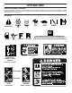
OPERATION KNOW YOUR SNOW THROWER READ THIS OWNER'S MANUAL AND ALL SAFETY RULES BEFORE OPERATING YOUR SNOW THROWER. Compare the illustrations with your snow thrower to familiarize yourself with the location of various controls and adjustments. Save this manual for future reference. These symbols may appear on your snow thrower or in literature supplied with the product. Learn and understand their meaning.
OPERATION SAFETY IGNITION KEY SPARK PLUG ENGINE OIL CAP WITH DIPSTICK AUGER CONTROL LEVER GASOLINE FILLER CAP DISCHARGE CHUTE CONTROL LEVER DRIVE SPEED CONTROL LEVER CHUTE DEFLECTOR CHOKE CONTROL FUEL SHUT-OFF VALVE THROTTLE / ENGINE CONTROL DISCHARGE CHUTE RECOIL STARTER HANDLE PRIMER OIL DRAIN PLUG HANDLE KNOB CLEANOUT TOOL MUFFLER NOTE: ITEMS ABOVE ARE SHOWN IN THEIR TYPICAL LOCATION ON THE ENGINE. ACTUAL LOCATION MAY VARY WITH THE ENGINE ON YOUR UNIT. TOOLBOX SKID PLATE AUGERS FIG.
OPERATION The operation of any snow thrower can result in foreign objects thrown into the eyes, which can result in severe eye damage. Always wear safety glasses or eye shields while operating your snow thrower or performing any adjustments or repairs. We recommend standard safety glasses or a wide vision safety mask worn over spectacles. 00155 TO USE CHOKE CONTROL (See Fig. 11) The choke control is located on the engine. Use the choke control whenever you are starting a cold engine.
OPERATION • HIGH POSITION • Make sure the discharge chute is pointed in a safe direction (no vehicles, buildings, people, or other objects are in the direction of discharge) before restarting the engine. Restart the engine, then squeeze the auger control lever to the handle to clear snow from the auger housing and the discharge chute. DISCHARGE CHUTE KNOB CLEAN-OUT TOOL CHUTE DEFLECTOR LOW POSITION MOUNTING CLIP FIG. 13 TO THROW SNOW (See Fig.
OPERATION TO ADJUST SKID PLATES (See Fig. 17) NOTE: The wrench provided in your parts bag may be used to adjust the skid plates. Skid plates are located on each side of the auger housing and adjust the clearance between the scraper bar and the ground surface. Adjust skid plates evenly to proper height for current surface conditions.
OPERATION SNOW THROWING TIPS TO START ENGINE • Be sure fuel shut-off valve is in the “OPEN” position. Your snow thrower engine is equipped with a recoil starter. COLD START 1. Insert safety ignition key (packed separately in parts bag) into ignition slot until it clicks. DO NOT turn the key. Keep the extra safety ignition key in a safe place. 2. Place throttle control in “FAST” position. 3. Rotate choke control to “FULL” position. 4.
MAINTENANCE GENERAL RECOMMENDATIONS The warranty on this snow thrower does not cover items that have been subjected to operator abuse or negligence. To receive full value from the warranty, operator must maintain snow thrower as instructed in this manual. Some adjustments will need to be made periodically to properly maintain your snow thrower. All adjustments in the Service and Adjustments section of this manual should be checked at least once each season.
MAINTENANCE AUGER GEAR CASE • The gear case was filled with lubricant to the proper level at the factory. The only time the lubricant needs attention is if service has been performed on the gear case. • If lubricant is required, use only Ronex ED #1 grease. • Oil will drain more freely when warm. • Catch oil in a suitable container. NOTE: The left side wheel may be removed from snow thrower for easier access to the oil drain plug and placement of a suitable container.
SERVICE AND ADJUSTMENTS WARNING: To avoid serious injury, before performing any service or adjustments: 1. Be sure throttle is in STOP position. 2. Remove safety ignition key. 3. Make sure the augers and all moving parts have completely stopped. 4. Disconnect spark plug wire from spark plug and place wire where it cannot contact plug. SNOW THROWER 3. Align holes in impeller hub with holes in impeller shaft and install two (2) new 1/4-20 x 1-5/8" capscrew/shear bolts.
SERVICE AND ADJUSTMENTS TO REPLACE BELTS (See Fig. 21) The auger and traction drive belts are not adjustable. If the belts are damaged or begin to slip from wear, they should be replaced. It is recommended that the belt(s) be replaced by a Sears service centre/department. NOTE: It is recommended that both the auger and traction drive belt be replaced at the same time.
SERVICE AND ADJUSTMENTS NOTE: To seal punctures or prevent flat tires due to slow leaks, tire sealant may be purchased from your local parts dealer. Tire sealant also prevents tire dry rot and corrosion. TO REMOVE WHEELS (See Fig. 22) • Remove the klik pin and remove wheel from axle. IMPORTANT: When installing wheel, be sure to use the innermost hole in axle and the wheel hub hole.
STORAGE OTHER • • • • • Cover your snow thrower with a suitable protective cover that does not retain moisture. Do not use plastic. Plastic cannot breathe, which allows condensation to form and will cause your snow thrower to rust. IMPORTANT: Never cover snow thrower while engine/ exhaust area is still warm. Remove safety ignition key; store it in a safe place. Do not store gasoline from one season to another. Replace your gasoline can if your can starts to rust.
REPAIR PARTS SNOW THROWER - MODEL PR524 (96192001503) AUGER HOUSING / IMPELLER ASSEMBLY 20
REPAIR PARTS SNOW THROWER - MODEL PR524 (96192001503) AUGER HOUSING / IMPELLER ASSEMBLY KEY PART NO. NO.
REPAIR PARTS SNOW THROWER - MODEL PR524 (96192001503) CONTROL PANEL / DISCHARGE CHUTE 1 19 2 2 2 6 26 27 28 4 20 5 25 6 16 29 13 14 27 9 7 18 3 21 30 17 31 12 14 34 8 10 15 8 07_Chute-knob_2 22
REPAIR PARTS SNOW THROWER - MODEL PR524 (96192001503) CONTROL PANEL / DISCHARGE CHUTE KEY PART NO. NO.
SNOW THROWER - MODEL PR524 (96192001503) REPAIR PARTS HANDLES 5 49 7 2 9 15 5 12 6 36 5 1 28 8 13 48 28 15 5 19 15 49 11 16 18 22 11 10 22 15 23 47 12 14 24 25 27 16 24 17 32 31 26 31 27 32 30 24 17
SNOW THROWER - MODEL PR524 (96192001503) REPAIR PARTS HANDLES KEY PART NO. NO.
SNOW THROWER - MODEL PR524 (96192001503) REPAIR PARTS DRIVE 5 2 4 4 4 2 7 5 2 2 8 4 4 9 10 2 27 14 13 5 22 12 2 16 21 24 20 41 18 17 7 44 32 15 4 23 18 44 6 19 2 5 4 25 43 11 15 29 22 34 41 33 26 28 36 38 39 40 31 30 22 26 35 33 37
SNOW THROWER - MODEL PR524 (96192001503) REPAIR PARTS DRIVE KEY PART NO. NO.
REPAIR PARTS SNOW THROWER - MODEL PR524 (96192001503) CHASSIS / ENGINE / PULLEYS 3 30 53 19 17 57 6 22 28 6 21 23 4 31 10 21 24 29 25 16 31 32 18 20 1 38 36 32 37 11 2 6 42 9 12 41 39 50 7 11 8 36 13 44 43 14 15 45 33 35 10 34 44 11 52 49 47 51 46 28 26 27
REPAIR PARTS SNOW THROWER - MODEL PR524 (96192001503) CHASSIS / ENGINE / PULLEYS KEY PART NO. NO.
SNOW THROWER - MODEL PR524 (96192001503) REPAIR PARTS WHEELS / DECALS 2 1 5 4 6 7 5 3 6 7 2 7 1 2 4 9 8 6 5 1 3 30 7
SNOW THROWER - MODEL PR524 (96192001503) REPAIR PARTS WHEELS / DECALS KEY PART NO. NO. 1 2 3 4 5 6 7 187831X421 155443 187866X421 146315 179830 174697 17490508 KEY PART NO. NO.
LIMITED WARRANTY The Manufacturer warrants to the original consumer purchaser that this product as manufactured is free from defects in materials and workmanship. For a period of two (2) years from date of purchase by the original consumer purchaser, we will repair or replace, at our option, without charge for parts or labor incurred in replacing parts, any part which we find to be defective due to materials or workmanship. This Warranty is subject to the following limitations and exclusions. 1.