IMPORTANT MANUAL Do Not Throw Away 04040 OWNER'S MANUAL MODEL: PP16H36RB WARNING: Read this Manual and follow all Warnings and Safety Instructions. Failure to do so can result in serious injury. LAWN TRACTOR ALWAYS WEAR EYE PROTECTION DURING OPERATION Visit our website: www.poulan-pro.com 532 42 87-61 05.12.09 TH Printed in U.S.A.
SAFETY RULES Safe Operation Practices for Ride-On Mowers DANGER: THIS CUTTING MACHINE IS CAPABLE OF AMPUTATING HANDS AND FEET AND THROWING OBJECTS. FAILURE TO OBSERVE THE FOLLOWING SAFETY INSTRUCTIONS COULD RESULT IN SERIOUS INJURY OR DEATH. • WARNING: In order to prevent accidental starting when setting up, transporting, adjusting or making repairs, always disconnect spark plug wire and place wire where it cannot contact spark plug.
SAFETY RULES Safe Operation Practices for Ride-On Mowers III. CHILDREN GENERAL SERVICE • Never operate machine in a closed area. • Keep all nuts and bolts tight to be sure the equipment is in safe working condition. • Never tamper with safety devices. Check their proper operation regularly. • Keep machine free of grass, leaves, or other debris build-up. Clean oil or fuel spillage and remove any fuelsoaked debris. Allow machine to cool before storing.
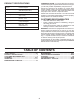
PRODUCT SPECIFICATIONS Gasoline Capacity and type: 2.0 Gallons Unleaded Regular Oil Type (API-SG-SL): SAE 30 (above 32°F) SAE 5W-30 (below 32°F) Oil Capacity: 48 oz. (1.4 L) Spark Plug: Champion RC12YC (Gap: .030") Ground Speed (MPH): Forward: 0-5.2 Reverse: 0-2.9 Charging System: 3 Amps Battery 5 Amps Headlights Battery: AMP/HR: 28 MIN. CCA: 230 CASE SIZE:U1R Blade Bolt Torque: 27–35 FT. LBS. CONGRATULATIONS on your purchase of a new tractor.
UNASSEMBLED PARTS 3TEERINGª7HEEL 3EAT ª7ASHERªª ªXª ªXª ª 'AUGE ª+NOB Steering Wheel Insert "ATTERY Steering Boot Steering Wheel Adapter ª ª ,OCKª7ASHER ª+EPSª.
ASSEMBLY Your new tractor has been assembled at the factory with exception of those parts left unassembled for shipping purposes. To ensure safe and proper operation of your tractor all parts and hardware you assemble must be tightened securely. Use the correct tools as necessary to insure proper tightness. TOOLS REQUIRED FOR ASSEMBLY A socket wrench set will make assembly easier. Standard wrench sizes are listed.
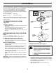
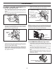
ASSEMBLY • First connect RED battery cable to positive (+) terminal with hex bolt and keps nut as shown. Tighten securely. • Connect BLACK grounding cable to negative (-) terminal with remaining hex bolt and keps nut. Tighten securely. • Replace battery cover. Open battery cover for: • Inspection for secure connections (to tighten hardware). • Inspection for corrosion. • Testing battery. • Jumping (if required). • Periodic charging .
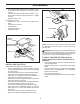
ASSEMBLY TO INSTALL BAGGER COMPONENTS TO TRACTOR (See Figs. 4A-4D) • • • Remove discharge chute from rear of tractor. Unhook the two (2) straps and pull chute out and away from tractor. Remove the two (2) 3/8 nuts and flat washers from the bolts at the tractor back plate. Replace discharge chute into rear opening of tractor. Secure the chute with the two hook straps.
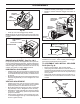
ASSEMBLY • • SPREADER BARS RETAINER SPRING Install and carefully lower bagger to actuate latch. Measure distance between bagger and latch as shown. 6MM (1/4") - 9MM (3/8") VINYL BINDING HORIZONTAL ADJUSTMENT BRACKET RETAINER SPRING 02 TOP SURFACES EVEN 6 90 VERTICAL ADJUSTMENT BRACKET Fig. 5B • Push cap over end of bagger dump handle. NOTE: For future use, the clevis pin may be removed in order to use the handle to clear the chute in the event it has become clogged. FIG.
ASSEMBLY ✓CHECKLIST CHECK TIRE PRESSURE BEFORE YOU OPERATE YOUR NEW TRACTOR, WE WISH TO ASSURE THAT YOU RECEIVE THE BEST PERFORMANCE AND SATISFACTION FROM THIS QUALITY PRODUCT. PLEASE REVIEW THE FOLLOWING CHECKLIST: ✓ All assembly instructions have been completed. ✓ No remaining loose parts in carton. ✓ Battery is properly prepared and charged. ✓ Seat is adjusted comfortably and tightened securely. ✓ All tires are properly inflated. (For shipping purposes, the tires were overinflated at the factory).
OPERATION These symbols may appear on your tractor or in literature supplied with the product. Learn and understand their meaning.
OPERATION KNOW YOUR TRACTOR READ THIS OWNER'S MANUAL AND SAFETY RULES BEFORE OPERATING YOUR TRACTOR Compare the illustrations with your tractor to familiarize yourself with the locations of various controls and adjustments. Save this manual for future reference.
OPERATION The operation of any tractor can result in foreign objects thrown into the eyes, which can result in severe eye damage. Always wear safety glasses or eye shields while operating your tractor or performing any adjustments or repairs. We recommend a wide vision safety mask over spectacles or standard safety glasses. 00155 NOTE: Under certain conditions when tractor is standing idle with the engine running, hot engine exhaust gases may cause “browning” of grass.
OPERATION • • • Adjust mower to desired cutting height (See “TO ADJUST MOWER CUTTING HEIGHT” in the Operation section of this manual). With mower in desired height of cut position, gauge wheels should be assembled so they are slightly off the ground. Install gauge wheel in appropriate hole with shoulder bolt, 3/8 washer, and 3/8-16 locknut and tighten securely. Repeat for opposite side installing gauge wheel in same adjustment hole.
OPERATION • Do not push or tow tractor at more than two (2) MPH. • To reengage transmission, reverse above procedure. NOTE: To protect hood from damage when transporting your tractor on a truck or a trailer, be sure hood is closed and secured to tractor. Use an appropriate means of tying hood to tractor (rope, cord, etc.). CAUTION: Wipe off any spilled oil or fuel. Do not store, spill or use gasoline near an open flame.
OPERATION MOWING TIPS • Place the motion control lever in neutral. Release the parking brake and let the clutch/brake slowly return to operating position. • Allow one minute for transmission to warm up. This can be done during the engine warm up period. • The attachments can also be used during the engine warmup period after the transmission has been warmed up.
OPERATION TO DUMP BAGGER (See Fig.16) Your tractor is equipped with a Dump Bag Alarm. To turn off the alarm disengage the attachment clutch switch. • Position tractor in location you wish to dump bagger. • Place motion control lever in Neutral position and set parking brake. • Raise dump handle to its highest position. Pull handle forward to raise bagger and dump clippings. • To continue mowing, be sure bagger is down and in proper operating position which will allow mower to operate.
MAINTENANCE MAINTENANCE SCHEDULE BEFORE EACH USE EVERY 8 HOURS EVERY 25 HOURS EVERY 50 HOURS EVERY 100 HOURS EVERY SEASON BEFORE STORAGE Check Brake Operation Check Tire Pressure T Check Operator Presence & ROS Systems R A Check for Loose Fasteners C Check/Replace Mower Blades T Lubrication Chart 0 Check Battery Level R Clean Battery and Terminals 3 4 Check Transaxle Cooling Check Mower Levelness Check V-Belts Check Engine Oil Level Change Engine Oil (with oil filter) 1,2 Change Engine Oil (wi
MAINTENANCE TRACTOR BLADE CARE (See Fig. 19) For best results mower blades must be kept sharp. Replace bent or damaged blades. Always observe safety rules when performing any maintenance. BRAKE OPERATION If tractor requires more than five (5) feet to stop at highest speed in highest gear on a level, dry concrete or paved surface, then brake must be checked and adjusted. (See “TO ADJUST BRAKE” in the Service and Adjustments section of this manual).
MAINTENANCE TRANSAXLE PUMP FLUID The transaxle was sealed at the factory and fluid maintenance is not required for the life of the transaxle. Should the transaxle ever leak or require servicing, contact your nearest authorized service center/department. BLADE MANDREL ASSEMBLY FLAT WASHER BLADE BOLT LEFT HAND THREADED ENGINE LH 6 STAR PATTERN LUBRICATION 6 STAR CENTER HOLE LOCK WASHER Only use high quality detergent oil rated with API service classification SG-SL.
MAINTENANCE • • • • • • Unlock drain valve by pushing inward and turning counterclockwise. To open, pull out on the drain valve. After oil has drained completely, close and lock the drain valve by pushing inward and turning clockwise until the pin is in the locked position as shown. Remove the drain tube and replace the cap onto to the bottom fitting of the drain valve. Refill engine with oil through oil fill dipstick tube. Pour slowly. Do not overfill.
SERVICE AND ADJUSTMENTS WARNING: TO AVOID SERIOUS INJURY, BEFORE PERFORMING ANY SERVICE OR ADJUSTMENTS: • Depress clutch/brake pedal fully and set parking brake. • Place motion control lever in neutral (N) position. • Place attachment clutch in “DISENGAGED” position. • Turn ignition key to “STOP” and remove key. • Make sure the blades and all moving parts have completely stopped. • Disconnect spark plug wire from spark plug and place wire where it cannot come in contact with plug.
SERVICE AND ADJUSTMENTS BOTTOM EDGE OF MOWER TO GROUND “A” • BOTTOM EDGE OF MOWER TO GROUND 00598 • “A” GROUND LINE • Fig. 25 To raise front of mower, loosen nut “F” from trunnion on both front links. Tighten nut “E” on both front links an equal number of turns. The two front links must remain equal in length. When distance “D” is 1/8" to 1/2" lower at front than rear, tighten nut “F” against trunnion on both front links. Recheck side-to-side adjustment.
SERVICE AND ADJUSTMENTS TO CHECK BRAKE CLUTCH If tractor requires more than five (5) feet to stop at highest speed in highest gear on a level, dry concrete or paved surface, then brake must be serviced. You may also check brake by: 1. Park tractor on a level, dry concrete or paved surface, depress brake pedal all the way down and engage parking brake. 2. Disengage transmission by placing freewheel control in “transmission disengaged” position.
SERVICE AND ADJUSTMENTS TO ADJUST STEERING WHEEL ALIGNMENT TO REMOVE CABLES, REVERSE ORDER • BLACK cable first from chassis and then from the fully charged battery. • RED cable last from both batteries. If steering wheel crossbars are not horizontal (left to right) when wheels are positioned straight forward, remove steering wheel and reassemble per instructions in the Assembly section of this manual. FRONT WHEEL TOE-IN/CAMBER The front wheel toe-in and camber are not adjustable on your tractor.
STORAGE ENGINE Immediately prepare your tractor for storage at the end of the season or if the tractor will not be used for 30 days or more. FUEL SYSTEM IMPORTANT: IT IS IMPORTANT TO PREVENT GUM DEPOSITS FROM FORMING IN ESSENTIAL FUEL SYSTEM PARTS SUCH AS CARBURETOR, FUEL FILTER, FUEL HOSE, OR TANK DURING STORAGE. ALSO, EXPERIENCE INDICATES THAT ALCOHOL BLENDED FUELS (CALLED GASOHOL OR USING ETHANOL OR METHANOL) CAN ATTRACT MOISTURE WHICH LEADS TO SEPARATION AND FORMATION OF ACIDS DURING STORAGE.
TROUBLESHOOTING POINTS PROBLEM CAUSE CORRECTION Will not start 1. 2. 3. 4. 5. 6. 7. Out of fuel. Engine not “CHOKED” properly. Engine flooded. Bad spark plug. Dirty air filter. Dirty fuel filter. Water in fuel. 1. 2. 3. 4. 5. 6. 7. 8. 9. Loose or damaged wiring. Carburetor out of adjustment. 8. 9. 10. Engine valves out of adjustment. 10. Fill fuel tank. See “TO START ENGINE” in Operation section. Wait several minutes before attempting to start. Replace spark plug. Clean/replace air filter.
TROUBLESHOOTING POINTS PROBLEM CAUSE CORRECTION Engine continues to run when operator leaves seat with attachment clutch engaged 1. Faulty operator-safety presence control system. 1. Check wiring, switches and connections. If not corrected, contact an authorized service center/ department. Poor cut - uneven 1. 2. 3. 4. 5. Worn, bent or loose blade. Mower deck not level. Buildup of grass, leaves, and trash under mower. Bent blade mandrel.
REPAIR PARTS TRACTOR--MODEL NO. PP16H36RB (96061015703), PRODUCT NO. 960 61 01-57 SCHEMATIC SCH08 12VDC AMMETER (OPTIONAL) RED STARTER RED RED A STARTER SOLENOID BATTERY M FUSE WHITE BLACK S B BL K AC M A1 G BLACK L A2 FBI SWITCH FBI BUZZER CLUTCH / BRAKE (PEDAL UP) ATT'MENT CLUTCH (CLUTCH OFF) RED GREEN OPERATOR PRESENCE RELAY ORANGE 85 86 BLACK 30 87 RED 87A GRAY HOUR METER BLACK (OPTIONAL) GRAY BLACK BLUE NOTE YOUR TRACTOR IS EQUIPPED WITH A SPECIAL ALTERNATOR SYSTEM.
REPAIR PARTS TRACTOR--MODEL NO. PP16H36RB (96061015703), PRODUCT NO.
REPAIR PARTS TRACTOR--MODEL NO. PP16H36RB (96061015703), PRODUCT NO. 960 61 01-57 ELECTRICAL KEY NO. PART NO.
REPAIR PARTS TRACTOR--MODEL NO. PP16H36RB (96061015703), PRODUCT NO.
REPAIR PARTS TRACTOR--MODEL NO. PP16H36RB (96061015703), PRODUCT NO. 960 61 01-57 CHASSIS AND ENCLOSURES KEY NO. PART NO.
REPAIR PARTS TRACTOR--MODEL NO. PP16H36RB (96061015703), PRODUCT NO.
REPAIR PARTS TRACTOR--MODEL NO. PP16H36RB (96061015703), PRODUCT NO. 960 61 01-57 DRIVE KEY NO. PART NO.
REPAIR PARTS TRACTOR--MODEL NO. PP16H36RB (96061015703), PRODUCT NO. 960 61 01-57 STEERING ASSEMBLY 38 97 34 39 1 41 42 37 37 36 44 88 91 43 71 67 68 46 29 67 8 6 13 2 17 82 65 46 6 87 5 8 87 40 68 32 5 29 4 3 43 11 15 29 33 34 35 10 43 95 8 steering_pl.
REPAIR PARTS TRACTOR--MODEL NO. PP16H36RB (96061015703), PRODUCT NO. 960 61 01-57 STEERING ASSEMBLY KEY NO. 1 2 3 4 5 6 8 10 11 13 15 17 29 32 33 34 35 36 37 38 39 40 41 42 43 44 46 65 67 68 71 82 87 88 91 95 97 PART NO.
REPAIR PARTS TRACTOR--MODEL NO. PP16H36RB (96061015703), PRODUCT NO. 960 61 01-57 SEAT ASSEMBLY 8 9 1 9 7 7 5 14 6 10 22 2 21 24 5 25 16 15 11 13 17 4 12 3 seat-CRD_knob_1 KEY NO. PART NO. DESCRIPTION 1 2 3 4 5 6 7 8 9 10 11 12 532 18 87-12 532 14 05-51 871 11 06-16 819 13 16-10 532 14 50-06 873 80 06-00 532 12 41-81 817 00 06-16 819 13 16-14 532 19 55-30 532 16 63-69 532 17 46-48 Seat Bracket Pnt Pivot Seat (blk ) Bolt Fin Hex 3/8-16 x 1 Washer Flat 13/32 x 1 x 10 Ga.
REPAIR PARTS TRACTOR--MODEL NO. PP16H36RB (96061015703), PRODUCT NO. 960 61 01-57 DECALS 5 3 7 18 15 9 8 6 14 11 13 14 17 8 11 4 2 _ 90N MAX + 11 20 12 1 KEY NO. PART NO. DESCRIPTION 1 2 3 4 5 6 7 8 9 10 11 12 532 40 03-89 532 40 88-17 532 18 61-63 532 19 68-41 532 18 61-64 532 16 88-69 532 17 27-43 532 42 87-75 532 12 44-33 532 14 50-05 532 18 21-66 532 15 97-37 Decal, Warning Syms. CE Decal, Hp Engine Decal, Hood RH Decal, Warning Eng. Syms.
REPAIR PARTS TRACTOR--MODEL NO. PP16H36RB (96061015703), PRODUCT NO. 960 61 01-57 ENGINE 3 2 72 1 81 13 4 78 38 32 14 44 78 46 33 37 31 33 45 29 23 OPTIONAL EQUIPMENT Spark Arrester engine-bs.
REPAIR PARTS TRACTOR--MODEL NO. PP16H36RB (96061015703), PRODUCT NO. 960 61 01-57 ENGINE KEY NO. PART NO.
REPAIR PARTS TRACTOR--MODEL NO. PP16H36RB (96061015703), PRODUCT NO. 960 61 01-57 MOWER 40 56 41 68 32 36 84 55 67 124 36 158 30 185 61 30 27 41 32 36 36 36 24 tc h_ m od _7 152 _c lu 42 46 21 17 44 33 26 30 30 32 2 21 23 33 5 31 25 21 30 32 21 40 21 28 3 18 31 124 297 254 6 21 41 4 35 1 19 2 295 41 116 117 119 296 36 41 21 34 119 116 21 117 21 22 46 2 124 130 18 13 15 2 46 2 45 131 11 14 69 8 9 36(92cm)_deck-elect.
REPAIR PARTS TRACTOR--MODEL NO. PP16H36RB (96061015703), PRODUCT NO. 960 61 01-57 MOWER KEY NO. PART NO.
REPAIR PARTS TRACTOR--MODEL NO. PP16H36RB (96061015703), PRODUCT NO. 960 61 01-57 MOWER LIFT 7 8 5 1 3 13 2 4 6 6 11 5 4 12 13 19 20 13 15 31 32 19 20 17 18 20 16 20 15 13 31 32 KEY NO. PART NO. DESCRIPTION 1 2 3 4 5 6 7 8 11 12 13 532 40 50-07 532 19 80-70 532 18 88-22 812 00 00-02 819 21 16-21 532 12 01-83 532 10 94-13 532 17 07-70 532 16 58-29 532 16 58-31 532 12 46-70 Plunger Asm. Lift LVR Shaft Asm. Lift Pin Groove E Ring #5133-62 Washer 21/32 x 1 x 21 Ga.
REPAIR PARTS TRACTOR--MODEL NO. PP16H36RB (96061015703), PRODUCT NO. 960 61 01-57 BAGGER ª ª ªª ª ªª ª ª ªª ª 15 33 34 36_mul ch plug (CRD) 35 "AGGERª!SYª #2$ ? ?R KEY NO. 1 3 4 5 6 7 8 9 10 11 12 13 14 15 16 17 19 20 21 22 24 25 PART NO.
SERVICE NOTES 46
SUGGESTED GUIDE FOR SIGHTING SLOPES FOR SAFE OPERATION FOL DA L O NG D THIS O I T S T A E D LIN 1 5 DEG E RE E S LOP E ONLY RIDE UP AND DOWN HILL, NOT ACROSS HILL 15 DEGREES MAX. WARNING: To avoid serious injury, operate your tractor up and down the face of slopes, never across the face. Do not mow slopes greater than 15 degrees. Make turns gradually to prevent tipping or loss of control. Exercise extreme caution when changing direction on slopes. 1. Fold this page along dotted line indicated above. 2.