
Operation Manual


6 - 30
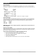
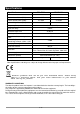
Rear Panel Features
1. Cooling Vents.
Front to rear forced airflow. Do not distruct
air vents.
2. Fuse.
This main fuse secures the amplifier and
wires against defects. Replace this only
with a fuse of same type and value.
3. Mains Power Connector.
4. Speaker Outputs NL4.
Minium load in stereo mode 4 Ohm per
channel. Pin +1 & +2 = + output, Pin -1 & -
2 = - output
5. Binding Post Output Jacks.
Minium load in stereo mode 4 Ohm per
channel. Minium load in bridge mode 8
Ohm.
6. Limiter Switch
Limiter for the automatic level limitation.
7. Mode Switch.
The amplifier can use 2 different modes:
stereo or bridge. Choose one of these
functions:
Stereo mode: Standard left/right stereo
mode.
Bridge mode: This mode combines both
amps on one channel which results in
double power on this channel. Connects
the signal to the left input channel and the
output level can now be adjusted with the
left volume control.
8. Ground Lift Switch.
Allows circuit and chassis grounds to be
separated in case of problems with earth
loops (hum).
9. Balanced 6.3mm Stereo Jack inputs.
Two 6.3mm jack female input connector
for connecting a signal source (mixer etc.).
10. Balanced XLR inputs.
Two 3-pin female XLR input connector for
connecting a signal source (mixer etc.).