
Datasheet

TOP242-250
36
I
4/03
General Information & Table of Contents
Product Selector Guide 1
Data Sheets 2
Application Notes 3
Design Ideas 4
Design Tools 5
Quality and Reliability 6
Package Information 7
DPA-Switch
DC-DC Seminar 8
LinkSwitch
&
TinySwitch-II
AC-DC Seminar 9
TOPSwitch-GX
AC-DC Seminar 10
Sales Representatives and Distributors 11
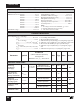
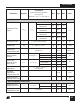
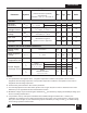
Conditions
(Unless Otherwise Specified)
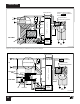
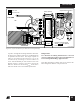
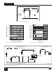
See Figure 53
SOURCE = 0 V; T
J
= -40 to 125 °C
Min Typ Max
Parameter
Symbol
Units
µA
µA
µA
µA
V
µA
µA
µA
µA
V
V
V
44 50 54
30
210 225 240
8
0.5 1.0 1.6
-35 -27 -20
5
300 400 520
-300 -240 -180
-110 -90 -70
1.90 2.50 3.00
2.30 2.90 3.30
1.26 1.33 1.40
1.18 1.24 1.30
1.24 1.31 1.39
1.13 1.19 1.25
T
J
= 25 °C
T
J
= 25 °C
Threshold
Hysteresis
T
J
= 25 °C
Threshold
Hysteresis
Line Under-Voltage
Threshold Current
and Hysteresis
(M or L Pin)
Line Over-Voltage
or Remote ON/
OFF Threshold
Current and Hys-
teresis (M or L Pin)
L Pin Voltage
Threshold
Remote ON/OFF
Negative Threshold
Current and Hyster-
esis (M or X Pin)
L or M Pin Short
Circuit Current
X or M Pin Short
Circuit Current
L or M Pin Voltage
(Positive Current)
X Pin Voltage
(Negative Current)
M Pin Voltage
(Negative Current)
Threshold
Hysteresis
MULTI-FUNCTION (M), LINE-SENSE (L) AND EXTERNAL CURRENT LIMIT (X) INPUTS
V
L
, V
M
= V
C
Normal Mode
Auto-restart Mode
l
L
or l
M
= 50 µA
l
L
or l
M
= 225 µA
l
X
= -50 µA
l
X
= -150 µA
l
M
= -50 µA
l
M
= -150 µA
l
UV
I
OV
V
L(TH)
I
REM (N)
I
L
(SC)
or
I
M (SC)
I
X
(SC)
or
I
M (SC)
V
L
, V
M
V
X
V
M
V
X
, V
M
= 0 V
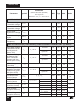
Auto-restart Upper
Threshold Voltage
Auto-restart Lower
Threshold Voltage
Auto-restart
Hysteresis Voltage
Auto-restart Duty
Cycle
Auto-restart
Frequency
V
C(AR)U
V
C(AR)L
V
C(AR)hyst
DC
(AR)
f
(AR)
5.8
4.5 4.8 5.1
0.8 1.0
48
1.0
V
V
V
%
Hz
SHUTDOWN/AUTO-RESTART