CH260-CH440 Service Manual IMPORTANT: Read all safety precautions and instructions carefully before operating equipment. Refer to operating instruction of equipment that this engine powers. Ensure engine is stopped and level before performing any maintenance or service.
Safety SAFETY PRECAUTIONS WARNING: A hazard that could result in death, serious injury, or substantial property damage. CAUTION: A hazard that could result in minor personal injury or property damage. NOTE: is used to notify people of important installation, operation, or maintenance information. WARNING Explosive Fuel can cause fires and severe burns. Do not fill fuel tank while engine is hot or running. Gasoline is extremely flammable and its vapors can explode if ignited.
Maintenance MAINTENANCE INSTRUCTIONS WARNING Accidental Starts can cause severe injury or death. Disconnect and ground spark plug lead(s) before servicing. Before working on engine or equipment, disable engine as follows: 1) Disconnect spark plug lead(s). 2) Disconnect negative (–) battery cable from battery.
Maintenance OIL RECOMMENDATIONS We recommend use of Kohler oils for best performance. Other high-quality detergent oils (including synthetic) of API (American Petroleum Institute) service class SJ or higher are acceptable. Select viscosity based on air temperature at time of operation as shown in table below. STORAGE If engine will be out of service for 2 months or more follow procedure below. 1. Add Kohler PRO Series fuel treatment or equivalent to fuel tank.
Specifications CH260/CH270 Engine Dimensions Dimensions in millimeters. Inch equivalents shown in [ ]. 17 690 01 Rev. F KohlerEngines.
Specifications CH260/CH270 Engine Dimensions Dimensions in millimeters. Inch equivalents shown in [ ]. 6 KohlerEngines.com 17 690 01 Rev.
Specifications CH395 Engine Dimensions Dimensions in millimeters. Inch equivalents shown in [ ]. 17 690 01 Rev. F KohlerEngines.
Specifications CH395 Engine Dimensions Dimensions in millimeters. Inch equivalents shown in [ ]. 8 KohlerEngines.com 17 690 01 Rev.
Specifications CH440 Engine Dimensions Dimensions in millimeters. Inch equivalents shown in [ ]. 17 690 01 Rev. F KohlerEngines.
Specifications CH440 Engine Dimensions Dimensions in millimeters. Inch equivalents shown in [ ]. 10 KohlerEngines.com 17 690 01 Rev.
Specifications ENGINE IDENTIFICATION NUMBERS Kohler engine identification numbers (model, specification and serial) should be referenced for efficient repair, ordering correct parts, and engine replacement. Model . . . . . . . . . . . . . . . . . . . . . CH260 Command Engine Horizontal Shaft Numerical Designation Specification . . . . . . . . . . . . . . . CH260-0001 Serial . . . . . . . . . . . . . . . . . . . . .
Specifications TORQUE SPECIFICATIONS3,5 CH260/CH270 Crankcase Oil Drain Plug Closure Plate Screw Cylinder Head Fastener (torque in 2 increments) CH395 CH440 18 N·m (13 ft. lb.) 24 N·m (212 in. lb.) First to 12 N·m (106 in. lb.) Finally to 24 N·m (212 in. lb.) Electric Starter Mounting Screw First to 18 N·m (159 in. lb.) Finally to 36 N·m (319 in. lb.) 24 N·m (212 in. lb.
Specifications TORQUE SPECIFICATIONS3,5 CH260/CH270 Rocker Arm Stud Pivot Jam Nut CH440 13.6 N·m (120 in. lb.) 10 N·m (89 in. lb.) Valve Cover Fastener 10 N·m (89 in. lb.) CLEARANCE SPECIFICATIONS3 CH260/CH270 Camshaft Running Clearance Camshaft Bearing Surface O.D. New 13.975 mm (0.5502 in.) 13.90 mm (0.547 in.) Max. Wear Limit Cam Lobe Profile (minimum dimension, measured from base circle to top of lobe) Intake - New Max. Wear Limit Exhaust - New Max. Wear Limit Connecting Rod Crankpin End I.
Specifications CLEARANCE SPECIFICATIONS3 CH260/CH270 Crankcase Governor Cross Shaft Bore I.D. New Max. Wear Limit 6.000/6.024 mm (0.2362/0.2372 in.) 6.037 mm (0.2377 in.) Crankshaft End Play (free) Ball Bearing Internal Clearance CH440 8.000/8.024 mm (0.3150/0.3159 in.) 8.075 mm (0.3179 in.) 0.0508/0.254 mm (0.002/0.010 in.) 0.003/0.025 mm 0.005/0.020 mm 0.006/0.020 mm (0.0001/0.0010 in.) (0.0002/0.0008 in.) (0.0002/0.0008 in.) 29.975/29.989 mm 34.975/34.989 mm 24.975/24.989 mm (1.1801/1.1807 in.
Specifications CLEARANCE SPECIFICATIONS3 CH260/CH270 Ignition Spark Plug Gap Module Air Gap 0.009/0.016 mm (0.0003/0.0006 in.) Piston Pin Bore I.D. New 20.000/20.008 mm (0.7874/0.7877 in.) 20.05 mm (0.7894 in.) 19.992/19.998 mm 17.992/17.998 mm (0.7083/0.7084 in.) (0.7871/0.7873 in.) 17.95 mm (0.7067 in.) 19.95 mm (0.7854 in.) Piston Pin O.D. New Max. Wear Limit Top and Center Compression Ring Side Clearance New Bore Oil Control Ring-to-Groove Side Clearance Piston Thrust Face O.D. New Max.
Specifications CLEARANCE SPECIFICATIONS3 CH260/CH270 Valves and Valve Lifters Intake Valve Stem-to-Valve Guide Running Clearance 0.038/0.065 mm (0.0015/0.0026 in.) Exhaust Valve Stem-to-Valve Guide Running Clearance 0.085/0.112 mm (0.0033/0.0044 in.) Intake Valve Stem O.D. 5.50 mm New (0.217 in.) Max. Wear Limit Exhaust Valve Stem O.D. New Max. Wear Limit Intake Valve Stem to Guide New Max. Wear Limit Exhaust Valve Stem to Guide New Max.
Specifications GENERAL TORQUE VALUES English Fastener Torque Recommendations for Standard Applications Bolts, Screws, Nuts and Fasteners Assembled Into Cast Iron or Steel Grade 2 or 5 Fasteners Into Aluminum Size Grade 2 Tightening Torque: N·m (in. lb.) ± 20% 8-32 2.3 (20) 10-24 3.6 (32) 10-32 3.6 (32) 1/4-20 7.9 (70) 1/4-28 9.6 (85) 5/16-18 17.0 (150) 5/16-24 18.7 (165) 3/8-16 29.4 (260) 3/8-24 33.9 (300) Grade 5 Grade 8 2.8 (25) 4.5 (40) 4.5 (40) 13.0 (115) 15.8 (140) 28.3 (250) 30.
Tools and Aids Certain quality tools are designed to help you perform specific disassembly, repair, and reassembly procedures. By using these tools, you can properly service engines easier, faster, and safer! In addition, you’ll increase your service capabilities and customer satisfaction by decreasing engine downtime. Here is a list of tools and their source. SEPARATE TOOL SUPPLIERS Kohler Tools Contact your local Kohler source of supply. SE Tools 415 Howard St.
Tools and Aids TOOLS Description Hydraulic Valve Lifter Tool For removing and installing hydraulic lifters. Ignition System Tester For testing output on all systems, including CD. Inductive Tachometer (Digital) For checking operating speed (RPM) of an engine. Offset Wrench (K and M Series) For removing and reinstalling cylinder barrel retaining nuts. Oil Pressure Test Kit For testing/verifying oil pressure on pressure lubricated engines.
Tools and Aids FLYWHEEL HOLDING TOOL ROCKER ARM/CRANKSHAFT TOOL A flywheel holding tool can be made out of an old junk flywheel ring gear and used in place of a strap wrench. 1. Using an abrasive cut-off wheel, cut out a six tooth segment of ring gear as shown. 2. Grind off any burrs or sharp edges. 3. Invert segment and place it between ignition bosses on crankcase so tool teeth engage flywheel ring gear teeth.
Troubleshooting TROUBLESHOOTING GUIDE When troubles occur, be sure to check simple causes which, at first, may seem too obvious to be considered. For example, a starting problem could be caused by an empty fuel tank. Some general common causes of engine troubles are listed below and vary by engine specification. Use these to locate causing factors. Engine Cranks But Will Not Start ● Battery connected backwards. ● Blown fuse. ● Carburetor solenoid malfunction. ● Choke not closing.
Troubleshooting Engine Loses Power ● Dirty air cleaner element. ● Engine overheated. ● Excessive engine load. ● Restricted exhaust. ● Faulty spark plug(s). ● High crankcase oil level. ● Incorrect governor setting. ● Low battery. ● Low compression. ● Low crankcase oil level. ● Quality of fuel (dirt, water, stale, mixture). Engine Uses Excessive Amount of Oil ● Loose or improperly torqued fasteners. ● Blown head gasket/overheated. ● Breather reed broken. ● Clogged, broken, or inoperative crankcase breather.
Troubleshooting CRANKCASE VACUUM TEST WARNING WARNING Carbon Monoxide can cause severe nausea, fainting or death. Avoid inhaling exhaust fumes. Engine exhaust gases contain poisonous carbon monoxide. Carbon monoxide is odorless, colorless, and can cause death if inhaled. Rotating Parts can cause severe injury. Stay away while engine is in operation. Keep hands, feet, hair, and clothing away from all moving parts to prevent injury. Never operate engine with covers, shrouds, or guards removed.
Troubleshooting COMPRESSION TEST For Command Twins: A compression test is best performed on a warm engine. Clean any dirt or debris away from base of spark plug(s) before removing them. Be sure choke is off, and throttle is wide open during test. Compression should be at least 160 psi and should not vary more than 15% between cylinders. All other models: These engines are equipped with an automatic compression release (ACR) mechanism.
Air Cleaner/Intake AIR CLEANER These systems are CARB/EPA certified and components should not be altered or modified in any way. Quad-Clean™ Air Cleaner Components A B B C D E Air Cleaner Cover B Bail C Precleaner D Paper Element E Air Cleaner Base A Low-Profile Air Cleaner Components NOTE: Running engine with cover positioned for cold weather operation in normal conditions can damage engine.
Fuel System Typical carbureted fuel system and related components include: ● Fuel tank. ● Fuel lines. ● In-line fuel filter. ● Fuel tank filter. ● Carburetor. ● Fuel strainer screen in carburetor. FUEL RECOMMENDATIONS Refer to Maintenance. FUEL LINE Low permeation fuel line must be installed on carbureted Kohler Co. engines to maintain EPA and CARB regulatory compliance. FUEL FILTER Fuel Tank Filter (if equipped) A serviceable fuel tank filter is located under fuel tank cap, in filler neck.
Fuel System CARBURETOR WARNING Explosive Fuel can cause fires and severe burns. Do not fill fuel tank while engine is hot or running. These engines are equipped with a fixed main jet carburetor. Carburetor is designed to deliver correct fuelto-air mixture to engine under all operating conditions. Idle mixture is set at factory and cannot be adjusted.
Fuel System Troubleshooting-Carburetor Related Causes Condition Engine starts hard, runs rough, or stalls at idle speed. Engine runs rich (indicated by black, sooty exhaust smoke, misfiring, loss of speed and power, governor hunting, or excessive throttle opening). Possible Cause Low idle fuel mixture (some models)/ speed improperly adjusted. Clogged air cleaner. Choke partially closed during operation. Dirt under fuel inlet needle. Bowl vent or air bleeds plugged. Leaky, cracked, or damaged float.
Fuel System High Idle Speed (RPM) Adjustment A A High Idle Speed Adjusting Stop Screw NOTE: High idle speed is also specified by equipment manufacturer. Set according to recommendations. High idle speed for basic engines is 3600 RPM (± 150 RPM). 1. Set high idle speed by turning high idle speed adjusting stop screw in or out. Do not exceed 3750 RPM. Carburetor Servicing WARNING 3. Remove float pin and inlet needle. Seat for inlet needle is not serviceable and should not be removed. 4.
Governor System ● When engine is at rest, and throttle is in fast position, tension of governor spring holds throttle plate open. When engine is operating, governor gear assembly is rotating. Force applied by regulating pin against cross shaft tends to close throttle plate. Governor spring tension and force applied by regulating pin balance each other during operation, to maintain engine speed.
Lubrication System These engines use a splash lubrication system, supplying necessary lubrication to the crankshaft, camshaft, connecting rod and valve train components. Lubrication Components A B C A Dipstick C Oil Fill Plug B OIL RECOMMENDATIONS Refer to Maintenance. CHECK OIL LEVEL NOTE: To prevent extensive engine wear or damage, never run engine with oil level below or above operating range indicator on dipstick. Ensure engine is cool. Clean oil fill/dipstick areas of any debris. 1.
Electrical System SPARK PLUGS CAUTION Electrical Shock can cause injury. Do not touch wires while engine is running. Spark Plug Component and Details Inspection Inspect each spark plug as it is removed from cylinder head. Deposits on tip are an indication of general condition of piston rings, valves, and carburetor. Normal and fouled plugs are shown in following photos: Normal A B Plug taken from an engine operating under normal conditions will have light tan or gray colored deposits.
Electrical System ELECTRONIC IGNITION SYSTEM Carbon Fouled Inductive Discharge Ignition System H G D Battery Maintenance Regular maintenance is necessary to prolong battery life. Battery Test To test battery, follow manufacturer's instructions. 17 690 01 Rev. F J E F K Ignition Module A If battery charge is insufficient to turn over engine, recharge battery.
Electrical System Electronic Ignition Systems and Oil Sentry™ Tests 1. Disconnect cap from spark plug and attach it to terminal end of spark tester. Attach tester spring clip to a good ground, not to spark plug. Turn ignition/key switch ON and crank engine while observing firing tip of tester. Condition Tester is firing. Tester doesn't fire. Conclusion Ignition system is good. Install a new spark plug and try to start engine. If it still will not start, check other possible causes (fuel, compression, etc.
Electrical System 7. Set an ohmmeter to Rx1 scale and zero meter. Test ignition/key switch as follows. a. Trace two black leads from on/off switch and separate them from any connections. Connect ohmmeter leads to switch leads, and check for continuity in both switch positions. Condition Conclusion Continuity should be indicated when and only when switch is in OFF position. Replace switch for any other results. b.
Electrical System Wiring Diagram-3/4 Amp Charging System, Rectified Only C A B J G D I K E F H A Diode B Stator C Ignition Module D Spark Plug E Oil Float Switch F Oil Control Module G Key Switch H Starter Motor I Relay J Battery Fuse K 12 Volt Battery 36 KohlerEngines.com 17 690 01 Rev.
Electrical System 3/4/10/18 Amp Battery Charging Systems NOTE: Zero ohmmeters on each scale to ensure accurate readings. Voltage tests should be made with engine running at 3600 RPM - no load. Battery must be fully charged. Check specific gravity of battery. If low, recharge or replace battery as necessary. To test charging system for no charge to battery: 1. Separate bullet connector in white lead from rectifierregulator. Connect an ammeter from female terminal to positive (+) terminal of battery.
Electrical System Wiring Diagram-10/18 Amp Charging System, with Rectifier-Regulator A D C B J G K I E F H A Rectifier-Regulator B Stator C Ignition Module D Spark Plug E Oil Float Switch F Oil Control Module G Key Switch H Starter Motor I Relay J Battery Fuse K 12 Volt Battery 38 KohlerEngines.com 17 690 01 Rev.
Starter System NOTE: Do not crank engine continuously for more than 10 seconds. Allow a 60 second cool down period between starting attempts. Failure to follow these guidelines can burn out starter motor. NOTE: If engine develops sufficient speed to disengage starter but does not keep running (a false start), engine rotation must be allowed to come to a complete stop before attempting to restart engine.
Starter System 4. Use a known, good, fully-charged battery and jumper cables to test starter motor. Be sure transmission is in neutral and PTO is OFF. Remove heavy lead from post terminal on starter. Connect one end of positive jumper cable to post terminal and connect other end to positive terminal of battery. Connect one end of negative jumper cable to negative terminal of battery. Touch other end of negative jumper cable to a bare surface on crankcase or to starter housing.
Starter System G I E I H F I E Drive Assembly is Serviced F Shim G Relay (Solenoid) Nuts H Motor to Starter Drive Assembly I Four Screws Relay (Solenoid) Replacement CH395, CH440 1. Disconnect all lead wires from relay (solenoid). Note location for reassembly. 2. Remove screws securing relay (solenoid), and remove relay (solenoid) from starter assembly. 3. Install new relay (solenoid) to starter assembly and secure with screws. Torque screws to 3.2 N·m (28 in. lb.). 4.
Starter System RETRACTABLE STARTERS WARNING Uncoiling Spring can cause severe injury. Wear safety goggles or face protection when servicing retractable starter. Retractable starters contain a powerful, recoil spring that is under tension. Always wear safety goggles when servicing retractable starters and carefully follow instructions in Retractable Starter for relieving spring tension.
Starter System Remove Starter 1. Remove screws securing starter to blower housing. 2. Remove starter assembly. Rope Replacement NOTE: Do not allow pulley/spring to unwind. Enlist aid of a helper if necessary. Rope can be replaced without complete starter disassembly. 1. Remove starter assembly from engine. 2. Pull rope out approximately 12 in. and tie a temporary (slip) knot in it to keep it from retracting into starter. 3. Pull knot end out of handle, untie knot, and slide handle off. 4.
Disassembly/Inspection and Service WARNING Accidental Starts can cause severe injury or death. Disconnect and ground spark plug lead(s) before servicing. Before working on engine or equipment, disable engine as follows: 1) Disconnect spark plug lead(s). 2) Disconnect negative (–) battery cable from battery.
Disassembly/Inspection and Service Clean all parts thoroughly as engine is disassembled. Only clean parts can be accurately inspected and gauged for wear or damage. There are many commercially available cleaners that will quickly remove grease, oil, and grime from engine parts. When such a cleaner is used, follow manufacturer’s instructions and safety precautions carefully. Make sure all traces of cleaner are removed before engine is reassembled and placed into operation.
Disassembly/Inspection and Service CH260/CH270 Blower Housing/Control Panel Components F H G I E J D K C B A A Retractable Starter B Blower Housing C Lower Shield D Carburetor E Dampening Spring F Throttle Linkage G Governor Lever H Hex Flange Nut I Governor Spring J Throttle Lever K Upper Shield 46 KohlerEngines.com 17 690 01 Rev.
Disassembly/Inspection and Service CH395/CH440 Blower Housing/Control Panel Components L N M J I K F G G H E D B C A A Retractable Starter B Blower Housing C Lower Shield D Electric Starter E Upper Shield F Carburetor G Fuel Brackets H Throttle Lever I Pivot Lever J Governor Spring K Dampening Spring L Throttle Linkage M Governor Lever N Hex Flange Nut 17 690 01 Rev. F KohlerEngines.
Disassembly/Inspection and Service Remove External Throttle, Governor and Choke Linkage 1. Mark which hole location governor spring is in on each side. Remove nut and washer securing throttle control lever to crankcase. Unhook spring and remove lever. 2. Loosen nut securing governor lever to governor shaft. Lift off governor lever and remove carburetor throttle link and dampening spring. Remove Carburetor WARNING Explosive Fuel can cause fires and severe burns.
Disassembly/Inspection and Service Remove Control Panel and Electric Starter (if equipped) NOTE: To ease reassembly, label wires for proper reconnection as wiring colors may not match. 1. Disconnect wires from control panel to starter, Oil Sentry™, ignition module, and rectifier-regulator. 2. Remove screws securing control panel bracket to crankcase, and remove control panel. Note 2 ground wires secured by one screw. 3. Remove screws securing electric starter to crankcase, and remove electric starter.
Disassembly/Inspection and Service Valve Details D B C D C A E CH260/CH270 Valve Specifications Item Dimension Intake Exhaust 26.875-27.125 mm (1.0581-1.0679 in.) 24.875-25.125 mm (0.9793-0.9892 in.) 63.3-63.9 mm (2.4921-2.5157) 63.3-63.9 mm (2.4921-2.5157) A Head Diameter B Valve Length C Stem Diameter 5.5 mm (0.217 in.) 5.438 mm (0.214 in.) D Face/Seat Width - Maximum 2.0 mm (0.079 in.) 2.0 mm (0.079 in.) E Face/Seat Angle 89.5°-90.5° 89.5°-90.
Disassembly/Inspection and Service CH260/CH270 Flywheel/Ignition Components E D C A Remove Ignition Module Remove screws securing ignition module to crankcase. Remove module. B F G A Flywheel Retaining Nut B Drive Cup C Flywheel Fan D Ignition Module E Flywheel F Stator G Flywheel Shield CH395/CH440 Flywheel/Ignition Components Inspection Inspect flywheel for cracks and flywheel keyway for damage. Replace flywheel if it is cracked.
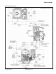
Disassembly/Inspection and Service CH260/CH270 Crankshaft/Camshaft/Closure Plate Components U V O L M R S N Q T P I J E H G C F D K A B A Closure Plate Oil Seal B Closure Plate C Closure Plate Bearing D Camshaft E Crankshaft F Piston Pin Retainer G Piston Pin H Piston I Connecting Rod End Cap J Connecting Rod K Piston Ring Set L Governor Cup M Governor Washer N Governor Shaft O Governor Gear P Oil Sentry™ Float Switch Q Tappet R Oil Sentry™ Wire S Crankcase B
Disassembly/Inspection and Service CH395/CH440 Crankshaft/Camshaft/Closure Plate Components X U Y V S T W R Q H I F G K J D L E C M N O P A B A Closure Plate Oil Seal B Closure Plate C Closure Plate Bearing D Closure Plate Balance Shaft Bearing E Balance Shaft F Governor Shaft G Governor Washer H Governor Gear I Governor Cup J Crankshaft K Connector Rod End Cap L Connector Rod M Piston Pin Retainer N Piston Pin O Piston P Piston Ring Set Q Camshaft R Oil
Disassembly/Inspection and Service Remove Closure Plate NOTE: Do not pry on gasket surface of crankcase or closure plate, as this can cause damage and leakage. 1. Remove screws securing closure plate to crankcase. 2. Remove closure plate, gasket, and dowel pins (if required) from crankcase. 3. Remove shims from crankshaft and camshaft. Inspection Inspect main bearing surface for wear or damage (refer to Specifications). Replace closure plate if required.
Disassembly/Inspection and Service Measure cam lobe profile, A and B, using an outside micrometer and compare with specifications listed. Measure the camshaft journals, C, which fit in the ball bearings, for wear using a micrometer. Compare with specifications listed. Dimension B B Remove Piston, Connecting Rod and Crankshaft NOTE: If a carbon ridge is present at top of cylinder bore, use a ridge reamer to remove it before attempting to remove piston. 1. Remove screws securing end cap to connecting rod.
Disassembly/Inspection and Service Preignition is caused by a hot spot in combustion chamber such as glowing carbon deposits, blocked cooling fins, an improperly seated valve, or wrong spark plug(s). Replacement pistons are available in STD bore size, and 0.25 mm (0.010 in.) oversize. Replacement pistons include new piston ring sets and new piston pins. Replacement ring sets are also available separately for STD, and 0.25 mm (0.010 in.) oversize pistons. Always use new piston rings when installing pistons.
Disassembly/Inspection and Service Inspect crankshaft keyways. If worn or chipped, replacement of crankshaft will be necessary. Inspect crankpin for score marks or metallic pickup. Slight score marks can be cleaned with crocus cloth soaked in oil. If wear limits are exceeded, as stated in Specifications, it will be necessary to replace crankshaft. Remove Oil Sentry™ System 1. Remove nut securing Oil Sentry™ lead wire grommet assembly in crankcase. 2. Pull grommet assembly from inside of crankcase. 3.
Disassembly/Inspection and Service Honing Crosshatch Detail Clean Cylinder Bore After Honing Proper cleaning of cylinder walls following boring and/ or honing is very critical to a successful overhaul. Machining grit left in cylinder bore can destroy an engine in less than one hour of operation after a rebuild. Final cleaning operation should always be a thorough scrubbing with a brush and hot, soapy water.
Reassembly CH260/CH270 Crankshaft/Camshaft/Closure Plate Components U V O L M R S N Q T P I J E H G C F D K A B A Closure Plate Oil Seal B Closure Plate C Closure Plate Bearing D Camshaft E Crankshaft F Piston Pin Retainer G Piston Pin H Piston I Connecting Rod End Cap J Connecting Rod K Piston Ring Set L Governor Cup M Governor Washer N Governor Shaft O Governor Gear P Oil Sentry™ Float Switch Q Tappet R Oil Sentry™ Wire S Crankcase Bearing T Crankcase U
Reassembly CH395/CH440 Crankshaft/Camshaft/Closure Plate Components X U Y V S T W R Q H I F G K J D L E C M N O P A B A Closure Plate Oil Seal B Closure Plate C Closure Plate Bearing D Closure Plate Balance Shaft Bearing E Balance Shaft F Governor Shaft G Governor Washer H Governor Gear I Governor Cup J Crankshaft K Connector Rod End Cap L Connector Rod M Piston Pin Retainer N Piston Pin O Piston P Piston Ring Set Q Camshaft R Oil Sentry™ Float Switch S
Reassembly NOTE: Make sure engine is assembled using all specified torque values, tightening sequences, and clearances. Failure to observe specifications could cause severe engine wear or damage. Always use new gaskets. Install Governor Assembly CH260/CH270 Governor Details Install Crankcase Bearings and Oil Seals Details A A D B E C B C F A Outer Surface C Depth B Seal NOTE: Oil bearings liberally with engine oil when installing.
Reassembly CH440 Governor Details CH395 Governor Details B A C A C B D E D E F H F G G I J A Thrust Washer B Governor Gear C Pin Rim D Washer E Hitch Pin F Thrust Washer G Governor Cross NOTE: Governor gear shaft is pressed into closure plate and should not be removed. 1. Assemble governor gear pin into governor gear so pin rim is held in place by weight retainers. 2. Place thrust washer on governor gear shaft in closure plate. Push governor gear onto shaft. 3.
Reassembly 4. Pull governor gear up until it makes contact with ring, then place pin in cup, retaining rim with weights. 5. Push pin down, snapping ring into shaft groove. 6. Pull up slightly on governor gear to ensure assembly is installed correctly. 7. Install one thrust washer onto governor cross shaft and slide shaft up through inside of crankcase. 8. Install second flat washer onto shaft. Position shaft so flat index end of shaft faces to left (9 o'clock position) and insert hitch pin from PTO side.
Reassembly CH395/CH440 Torque Sequence CH395/CH440 Flywheel/Ignition Components 1 6 1 3 G H 4 5 4 2 D C 3 F B A E 2 7 NOTE: Make sure governor lever is against cup on governor gear assembly. 1. Check to make sure sealing surfaces of crankcase and closure plate are clean and free of nicks/burrs. 2. Install two dowel pins into locations shown in crankcase. Install new closure plate gasket (dry) onto dowel pins. 3. Install closure plate to crankcase.
Reassembly 1. Install woodruff key into keyway of crankshaft. Make sure key is properly seated and parallel with taper of shaft. 2. Install flywheel onto crankshaft, being careful not to shift position of woodruff key. 3. Install flywheel shield and secure with one screw (CH260 and CH270 only). 4. Install fan bosses into matching holes in flywheel. 5. Position drive cup on flywheel, engaging boss on its base with corresponding hole in flywheel. Hold in position and install nut.
Reassembly Assemble Cylinder Head NOTE: Engine utilizes valve stem seals on valves. Always use a new seal when valves are installed in cylinder head. Never reuse old seals. 1. Install valves into their respective positions. 2. Install new valve seals on stem of valves. 3. Install valve springs and retainers into their respective locations in cylinder head. Support valve heads from underneath. Using hand pressure, compress each valve spring and slide each retainer onto valve stem to lock in place.
Reassembly CH260/CH270 Blower Housing/Control Panel Components F H G I E J D K C B A A Retractable Starter B Blower Housing C Lower Shield D Carburetor E Dampening Spring F Throttle Linkage G Governor Lever H Hex Flange Nut I Governor Spring J Throttle Lever K Upper Shield 17 690 01 Rev. F KohlerEngines.
Reassembly CH395/CH440 Blower Housing/Control Panel Components L N M J I K F G G H E D B C A A Retractable Starter B Blower Housing C Lower Shield D Electric Starter E Upper Shield F Carburetor G Fuel Tank Brackets H Throttle Lever I Pivot Lever J Governor Spring K Dampening Spring L Throttle Linkage M Governor Lever N Nut 68 KohlerEngines.com 17 690 01 Rev.
Reassembly Install Fuel Tank Supports and Shut Down Switch with Bracket CH260, CH270 1. Position both tank support brackets on crankcase and loosely install with screws. 2. Position shut down switch with bracket on tank bracket and install threaded stud to secure. 3. Torque tank support bracket hardware to 24 N·m (212 in. lb.). CH395, CH440 NOTE: Threaded stud and bracket with shut down switch should not be removed. Position both tank support brackets on crankcase and install with screws.
Reassembly CH260/CH270 Governor Lever Hole Position/RPM Chart 3 2 1 Engine Speed RPM 3801-4000 3601-3800 3401-3600 3201-3400 3001-3200 2801-3001 CH440 Governor Lever Hole Position/RPM Chart 1 2 3 4 A B C 8-12% Droop Spring Hole Color Combination Red #3-A Red #3-A Red #2-A Yellow #2-A Yellow #1-A Yellow #1-B 5-8% Droop Spring Hole Color Combination Yellow #2-A Black #1-B Engine Speed RPM 3801-4000 3601-3800 3401-3600 3201-3400 3001-3200 2801-3001 A B C 6-12% Droop Spring Hole Color Combination No
Reassembly External Engine Components H D I J E F G C B K A A Oil Drain Plug B CH395, CH440 Muffler Assembly C Breather Hose D Quad-Clean™ Cover E Quad-Clean™ Element/Precleaner F Quad-Clean™ Base G Carburetor Shroud H Fuel Tank I Fuel Line J CH260, CH270 Muffler Assembly K Low-Profile Air Cleaner 17 690 01 Rev. F KohlerEngines.
Reassembly Install Oil Sentry™ Module NOTE: If Oil Sentry™ module is mounted inside control panel, skip this step. 1. Install Oil Sentry™ module and secure with screw. Torque screw to 3.5 N·m (31 in. lb.). 2. Connect electrical leads for Oil Sentry™ module. Install Fuel Tank 1. Position fuel tank on mounting brackets. Secure with screws on inner mounting bracket and on PTO side strap. 2. Install nuts on fuel tank studs. 3. Torque side strap screw to 10 N·m (89 in. lb.). 4.
17 690 01 Rev. F KohlerEngines.
KohlerEngines.com 17 690 01 Rev.
17 690 01 Rev. F KohlerEngines.
© 2012 by Kohler Co. All rights reserved. 76 KohlerEngines.com 17 690 01 Rev.