
Engine Service Manual
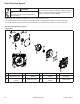
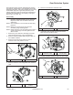
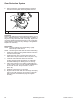
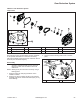
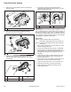
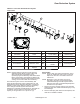
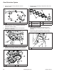
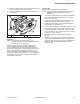
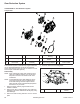
Table Of Contents

57
Gear Reduction System
17 690 01 Rev. J KohlerEngines.com
F
E
D
B
A
C
G
H
I
J
K
L
M
N
O
P
R
Q
S
T
U
V
W
Y
A
X
Z
AA
A Oil Seal B Drain Plug C Reduction Cover D Crankshaft Bearing
E PTO Shaft F Chain G
Reduction Case
Cover Gasket
H Retainer Ring
I Weight Holder Pin J Clutch Holder Spring K Weight Holder L Clutch Weight
M Weight Retainer N Pressure Plate O Clutch Plate P Friction Disc
Q Clutch Center Gear R Clutch Cup S Drive Gear T Slide Bearing
U Thrust Washer V Reduction Case W
Reduction Case
Gasket
X Pinion Spacer
Y Closure Plate Z
Reduction Case
Dipstick
AA Clutch Assembly
CH270 2:1 with Clutch Gear Reduction System
Components
NOTE: Engines with this reduction system must be
operated at 2400 RPM or higher under load,
when full gear box engagement occurs.
Operating engine under heavy loads below 2400
RPM, could result in clutch/gear box failure from
disc slippage/overheating and insuffi cient engine
cooling, not covered under normal warranty.
This reduction system uses a clutch assembly and
chain and sprocket drive system, independent of, and
separated from main crankcase lubrication. Check and
maintain oil level using dipstick in gear box (reduction)
case. Change reduction system oil at interval in
maintenance schedule (see Maintenance). Use 20W-40
or 20W-50 oil in this gear box (reduction) case. Oil
capacity of this gear box is 0.5 L (0.52 U.S. qt.).
Disassembly
NOTE: Place a drain pan under gear reduction unit to
catch any residual oil when cover is removed.
Dispose of used oil in accordance with local
ordinances.
NOTE: Bearings in cover and clutch cup can be
removed if necessary using a bearing puller.
Crankshaft bearing removal requires closure
plate removal. Refer to Disassembly/Inspection
and Service for procedure.
1. Remove any drive coupling and key from reduction
assembly PTO shaft. Clean shaft and keyway of any
burrs/damage.
2. Remove drain plug and reduction case dipstick, and
drain oil into suitable container.
B