English - Español - Français - Deutsch - Italiano
INTRODUCTION Thank you for purchasing the NEW Power Probe III (PP3). The PP3 is our most revolutionary circuit tester to date. The PP3 literally speeds you through the diagnosing of 12 to 24 volt automotive electrical systems. After connecting the PP3’s clips to the vehicle’s battery, the automotive technician can determine at a glance, the voltage level and the polarity of a circuit with out running for a voltmeter or reconnecting hook-up clips from one battery pole to the other.
English Table of Contents Hook-up and quick self-test ............................................................................................................. 3 Turning the Audio Tone On & Off ................................................................................................... 3 Circuit Breaker ................................................................................................................................. 4 Voltage & Polarity testing ....................................
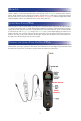
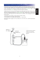
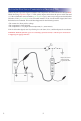
HOOK-UP Unroll the Power Probe cable. Connect the RED battery hook-up clip to the POSITIVE terminal of the vehicle’s battery. Connect the BLACK battery hook-up clip to the NEGATIVE terminal of the vehicle’s battery. When the PP3 is first connected to a battery (power source), it will sound a quick high and then low beep and go into “Power Probe Mode (PPM) (See Mode #1 on page 10) and the 2 bright white LEDs (dual head lights) will be on to illuminate the test area of the probe tip.
CIRCUIT BREAKER In Power Probe Mode (Mode #1) with a the circuit breaker tripped, the LCD will display the symbol “C B”. (see page 11-12 for detail) All other functions of the PP3 are still active. This means that you can still probe a circuit and observe the voltage reading. When the circuit breaker is tripped, the PP3 will NOT be able to conduct battery current to the tip even when the power switch is pressed.
CONTINUITY TESTING (PPM) While the PP3 is in Power Probe Mode, and by using the Power Probe tip in connection with chassis ground or the auxiliary ground lead, continuity can be tested on wires and components attached or disconnected from the vehicle’s electrical system. The PP3 indicates continuity using 2 resistance levels. When the Power Probe tip has a resistance to ground less than 20K Ohms but greater than 2K Ohms the LCD will indicate “0.0” volts but no Green “-” LED.
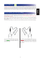
ACTIVATING COMPONENTS IN YOUR HAND (PPM) While keeping an eye on the green LED negative sign, quickly depress and release the power switch forward (+). If the green negative sign “-“ LED went out and the red positive sign “+” came on, you may proceed with further activation. If the green negative sign “-“ LED went off at that instant or if the circuit breaker tripped, the Power Probe has been overloaded.
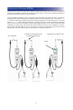
TESTING TRAILER LIGHTS AND CONNECTIONS (PPM) 1. Connect the PP3 to a good battery. 2. Clip the auxiliary ground clip to the trailer ground. 3. Probe the contacts at the jack and then apply voltage to them. This lets you check the function and orientation of the connector and trailer lights. If the circuit breaker tripped, that contact is likely a ground. Reset the circuit breaker by letting it cool down (15 sec.) and depressing the reset button until in clicks into place.
ACTIVATING COMPONENTS IN THE VEHICLE (PPM) • The contact is a direct ground. • The component is short-circuited. • The component is a high current component (i.e., starter motor). If the circuit breaker tripped, reset it by allowing it to cool down (15 sec.) and then depress the reset button. Warning: Haphazardly applying voltage to certain circuits can cause damage to a vehicle’s electronic components.
ACTIVATING ELECTRICAL COMPONENTS W/GROUND (PPM) Contact the probe tip to the negative terminal of the component, the LED indicator should light RED. While observing red positive sign “+” LED, quickly depress and release the power switch rearward (-). If the red indicator went out and the green negative sign (-) came on you may proceed with further activation. If the green indicator went off at that instant or if the circuit breaker tripped, the Power Probe has been overloaded.
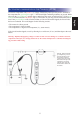
CHECKING FOR BAD GROUND CONTACTS (PPM) FOLLOWING & LOCATING SHORT CIRCUITS (PPM) In most cases a short circuit will appear by a fuse or a fusible link blowing or an electrical protection device tripping (i.e., a circuit breaker). This is the best place to begin the search. Remove the blown fuse from the fuse box. Use the Power Probe tip to activate and energize each of the fuse contacts. The contact which trips the PP3 circuit breaker is the shorted circuit.
MODES The Power Probe III has been designed to work the same as the previous Power Probe circuit testers. Using the advanced features and modes is optional. However, understanding them will expand your diagnosing capabilities. The LCD display indicates voltage levels of the circuit along with an identifying symbol showing you what mode it is in. The additional features contain 5 new modes which give you specific information about how the circuit is reacting.
Mode #5 Threshold Level Setting for the Peak to Peak Detection in Power Probe Mode” (Mode #1) This mode is only used to adjust the threshold voltage in “Power Probe Mode” for Peak to Peak Detection and Signal Monitoring. To set the threshold level for the peak to peak detection in “Power Probe Mode”, press and hold the mode button for one second until you hear a beep.
Power Probe 3 Specifi cations DC 0 – 70V + 1 digit P-P 0 – 70V Frequency response of tone pass through 10Hz to greater than 10 Khz PP display 15Hz Square Wave 35Hz Sine Wave Power Probe Mode – Continuity to ground First level – display is enabled less than 20K Second level – green LED is enabled less than 2K – & + Peak Detector Response Single event capture less than 200µs pulse width Repetitive events less than 1µs pulse width Peak to Peak Mode 0 – 70V + 1 digit 4Hz to over 500kHz Square Wave input 4Hz t
ROCKER SWITCH REPLACEMENT English