Installation Manual PS-225
Table of Contents Pre-Uncrating Checklist ............................................... 1 Verifying System Requirements .................................. 2 Verifying System Direction ................................................................... 2 Verifying the Electrical Requirements .................................................. 2 Removal of Existing Unit ............................................. 3 Existing Supply Lines .....................................................................
Plumbing Connections ....................................................................... 19 Electrical Connections ....................................................................... 20 Checking the Motor Rotation (“JOG” Feature) ................................... 20 Shelving ............................................................................................. 20 Validating the Installation ........................................... 21 Testing the Components ..............................
Pre-Uncrating Checklist PS-225 1
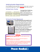
Verifying System Requirements Prior to completely removing the Power Soak unit from the crate, it is necessary to verify certain requirements. Remove only the lid of the crate at this time. Verifying System Direction The Power Soak can be built as a “Left to Right” or as a “Right to Left” configuration with a variety of options. Look inside the crate and verify that the configuration of the machine matches the specifications of the order description.
Removal of Existing Unit If the new Power Soak is not replacing an existing sink, skip this section. If the removal of an existing sink is necessary, continue with this section. Existing Supply Lines The water and electrical source must be shut off before disconnecting or cutting the water or electric lines. WARNING Failure to shut off the electrical and water supply will result in personal injury, including serious injury or death, and extensive equipment damage.
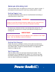
Pre-Plumbing Supply and Waste Lines The supply and waste lines must meet the following requirements: • Hot and cold water supply must be ½” diameter or larger. • Center lines of the hot and cold water supply must be 10” or less above the floor to access the shutoff valves when the machine is installed. • Waist drain must be 1-1/2” minimum diameter. • Center line of the waste drain must be 11” or less above the floor to allow the sink to drain properly.
Post-Uncrating Instructions PS-225 5
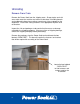
Uncrating Remove From Crate Remove the Power Soak from the shipping crate. Sharp staples and nails are used to crate the machine and care must be taken in handling boards and cardboard to keep from creating a puncture or injury to people or the equipment. Discard the crating materials in an appropriate disposal area or container. Inspect the sink and packages to be certain that there was no damage created by the shipping company.
Component Installation Lay the sink on its back to allow access to the bottom of the tanks. Be careful to not let the sink assembly drop on the floor with an impact that would damage the sink assembly or the floor. It may be necessary to place some cardboard or tarp on the floor to protect the finish. IMPORTANT Do not bend the edge of the backsplash when laying the sink on its back side.
Apply a generous bead of a drain sealant around the lip of the drain body. DRAIN BODY IMPORTANT APPROVED DRAIN SEALANT THE RIM OF THE DRAIN MUST SEAT ON THE SURFACE OF THE SINK OR IT WILL WORK LOOSE OVER TIME AND ALLOW WATER TO LEAK AROUND THE DRAIN The drains with built-in valves will be oriented with the handle connection toward the front of the sink. From inside the sink, insert the drain through the drain hole and seat the flange against the sheet metal surface of the tank.
Using two nuts, attach the drain handle bracket to the studs on the bottom of the tank. Insert the drain valve handle through the bracket and into the drain body. It may be necessary to rotate the handle a partial turn to align the flats on the end of the handle shaft with the flats on the valve so that the handle will fully insert into the valve. Secure the handle to the valve body by screwing the handle nut onto the valve body connection.
Install Legs The Power Soak is usually shipped without the leg assembly attached to the machine. Different options have different types of leg assemblies. Some leg assemblies are all welded together and others are pieces that need to be assembled. If the leg set is welded together, skip to the section labeled “Leg Set and Sink”. Leg Set Assembly Locate the two leg end weldments and stretcher. The stretcher is the horizontal tube that connects between the legs to provide lateral stability to the legs.
SET SCREWS ARE ORIENTED TOWARD THE INTERIOR OF THE SINK AND THE SOCKET IS ON TOP OF THE WELDED STRETCHER WELDED STRETCHER Leg Set and Sink Insert the leg assembly into the sockets on the bottom of the sink. Insert the leg set into the sanitizer sink (sanitizer sink is an option and may not be included). Be sure that all the legs are seated in the bottom of the sockets. Use an allen wrench (5/32) to tighten the set screws in all of the sockets.
JBZ Joint Installation If the unit is shipped in one piece, skip this section. If the unit is shipped as two separate pieces, continue with this section. Test Fit Dry fit the two sections of the sink together to be sure that the joint has not been damaged in shipping. The lip of the rinse tank will slide over the edge of the wash tank. Check the alignment and fit of the two sections. It may be necessary to adjust the leveling feet to achieve a correct fit.
Reassemble the two sections. Apply a bead of grey-colored NSF approved sealant (supplied with the unit) in the gap between the rinse sink and the trim plate. Seal the entire joint to keep liquids from entering. Bolt the channel rim and backsplash together using the nuts and bolts provided with the unit. BOLT THE JOINT TOGETHER UNDER THE FRONT RIM AND BEHIND THE BACK SPLASH.
Wiring Connections Machine Wiring Locate the two halves of the wiring harness and inspect them to be sure they are clean and not damaged. Insert the two halves together and hand tighten the threaded collar. HAND TIGHTEN THE COLLAR Optional Wireless Remote Alert Light System If the Power Soak unit was purchased with the Wireless Remote Alert Light System, refer to the instructions provided with the light system to complete the wiring for this devise.
Faucet Installation Open the faucet package and locate the water connection elbows, faucet body and escutcheon assemblies. Apply Teflon tape to the threads of the elbows and insert them though the backsplash of the sink. Escutcheon screwed onto the elbow Elbow inserted from the back side of the backsplash Wrap the elbow threads with Teflon tape Loosely fit the escutcheons to the elbows and the faucet body.
Intentionally blank page 16
Completing the Installation PS-225 17
Final Installation Steps Machine Placement Position the Power Soak so that the back splash rests against the wall and is placed according to the floor plan or customer’s selected location. Examine the drain and water supply lines to determine that the plumbing can be completed when the Power Soak is in the final location. Verify that the plumbing from the faucet can be reached with the sink against the wall.
Seal around the Backsplash and Screws Examine the installation to see that the wall and backsplash are clean and free of dust and oils. Seal the top and sides of the backsplash to the wall using the clear NSF approved sealant provided with the Power Soak. Seal around the screw heads to be sure they do not allow water to leak behind the backsplash. Wipe off all excess sealant leaving a smooth, clean and sanitary bead of sealant on all the edges.
Electrical Connections The final electrical connections between the Power Soak and the electrical supply must be made by a licensed electrician. The Power Soak has several options for motors and heater. Review the information tag for determining the specific requirements of the machine being installed (see Verify the Electric Requirements section of this instruction booklet).
Validating the Installation PS-225 21
Testing the Components Check for Leaks • • • Turn on the water supply and inspect all joints for leaks. Close the drain valve(s), fill the sink(s) with water and inspect the drain fittings for leaks. Open the drain valve(s) and inspect the drain joins for leaks as the water is draining from the sink. Check the Electrical Installation • • • Verify that there are no loose wires or open electrical enclosure. Fill the wash tank with water and press the START button to see that the motor will start.
Appendix 23
Power Soak is a registered trademark of Cantrell Industries, Inc. The Power Soak concept and design is fully patented. Power Soak Systems. Inc. 903 East 104th Street, Suite 130 Kansas City, MO 64131 Phone (816) 222-2400 Fax (816) 222-2419 (800) 444-9624 www.powersoak.