PURE SINE WAVE POWER INVERTER MODEL: PS1001 PS1002 PS1003 PS1004 PS1005
IMPORTANT SAFETY INSTRUCTIONS 1. This section contains important safety and operating instructions. Read and keep this user manual for future reference. 2. Do not expose the Pure sine inverter to rain, snow, or spray water. To reduce the risk of fire hazard, do not cover or obstruct the ventilation openings. Do not install the Pure sine inverter in a zero-clearance compartment. Overheating may result. 3.
WARNING : EXPLOSION HAZARD 1. Working in the vicinity of lead-acid batteries is dangerous. Batteries generate explosive gases during normal operation. Therefore, you must read this guide and follow the instructions before installing or using your inverter. 2. This equipment contains components which tend to produce arcs or sparks.
PRECAUTIONS WHEN WORKING WITH BATTERIES 1. Make sure the area around the battery is well ventilated. 2. Never smoke or allow a spark or flame near the engine or batteries. 3. Use caution to reduce the risk of dropping a metal tool on the battery. It could spark or short circuit the battery or other electrical parts and could cause an explosion. 4. Remove all metal items, like rings, bracelets, and watches when working with lead-acid batteries.
SPECIFICATIONS Item PS1001 PS1002 PS1005 PS1003 PS1004 Continuous output frequency 600W 1000W 1500W 2000W 3000W Surge power 1200W 2000W 3000W 4000W 6000W Input voltage range (12V) 10-16VDC Input under voltage activation (12V) 10.
SPECIFICATIONS (CONTINUED) Item Length of the remote controller wire PS1001 PS1002 PS1003 PS1004 15 ft. (4.6m) only for model PS1002 & PS1003 & PS1004 & PS1005 Intelligent cooling the fan starts to work when the load power is larger than 100W, does not work when no load or small load Fuse (outer car fuse) 40Ax2 Dimension (LxWxH) PS1005 40Ax4 The cooling fan on the product will not run when start up the inverter, it will start running only when the case temperature reaches about 40°C.
PRODUCT INFO This power inverter is an advanced tool of power conversion, and it can supply you with AC power converted from DC power source. Not only can it be used in cars, vessels, and camping vehicles, it can also be used in an emergency if the power fails. In order to use the inverter efficiently and safely, please install and use it in a proper way. Please read the instructions carefully before installing and using the appliance. WARNING AND SAFETY 1. 2. 3. 4. 5. 6. 7.
WARNING AND SAFETY (CONTINUED) 8. Disconnect the battery and inverter when it is not in use.
PS1002 PARTS LIST Chassis PS1002 9
PS1003, PS1004, PS 1005 PARTS LIST Chassis PS1003, PS1004, PS1005 10
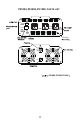
REMOTE CONTROL BOX Normal working indicator Power switch (Switch) Fault indicator Remote interface Connecting wire INSTALLATION AREA 1. Before installing the Pure sine inverter, the area or location MUST meet the following requirements: DRY - Do not allow water or other fluids to drip or splash on the Pure sine inverter. DO NOT MOUNT THE INVERTER IN AN AREA SUBJECT TO SPLASHING WATER AND SPRAY WATER. COOL - Normal air temperature should be between 32°F and 104°F (0°C and 40°C)- the cooler the better.
INSTALLATION AREA (CONTINUED) VENTILATION - Allow at least 5 inches (13cm) of space at the DC end of the Pure sine inverter for air flow, 1 inch (2.5cm) on each side, and 2 inches (5cm) at the AC end of the inverter. For cooling, the size of the space is not as important as the overall supply of air. The more clearance for ventilation around the unit, the better the performance. DO NOT allow the ventilation openings on the ends of the unit to become obstructed.
WARNING : FIRE & EXPLOSION HAZARD This equipment contains components that tend to produce arcs and sparks. To prevent fire or explosion, do not install the Pure sine inverter in compartments containing batteries or flammable materials or in locations that require ignition-protected equipment. This includes any space containing gasoline-powered machinery, fuel tanks, or joints, fittings, or other connections between components of the fuel system.
INSTALLATION OF REMOTE CONTROL BOX (For PS1002, PS1003, PS1004, & PS1005) 1. The remote is designed to be mounted on a dash or other flat surface. 2. The remote cable should be plugged into inverter and the remote before being mounted. NOTE: The remote is optional and not required for inverter operation. The main power switch will turn the power on/off.
HOW TO INSTALL THE DC CIRCUIT BREAKER (DC CIRCUIT BREAKER IS NOT INCLUDED) Before making the final DC connection, check cable polarity at both the battery and the Pure sine inverter. Positive must be connected to positive; negative must be connected to negative. Reversing the positive and nega tive battery cables will damage the Pure sine inverter and void your warranty. Operation of the inverter without a proper ground connection may result in an electrical safety hazard.
USING THE INVERTER PS1001 1. Check the output voltage and capacity of the battery. It should comply with the requirement of the product used. 2. Connect the battery and the DC cable of the inverter. Ensure that the polarities are not reversed and are in good contact. 3. Turn on the switch. The green LED power indicator light should be on. 4. Turn off electrical appliance and insert the electrical appliance plug to the AC output socket of the inverter. Turn on the electrical appliance for use. 5.
USING THE INVERTER (CONTINUED) PS1002, PS1003, PS1004, & PS1005 1. Check the output voltage and capacity of the battery. It should comply with the requirement of the product used. 2. Connect the battery and the DC cable of the inverter. Ensure that the polarities are not reversed and are in good contact. 3. Press and hold the power switch on the inverter or the remote control box for at least 5 seconds.
HOW TO USE THE USB POWER SUPPLY Models PS1001, PS1002, & PS1005 USB output can provide stable 5V DC voltage power. The maximum current is 1000mA (PS1003 & PS1004 maximum current is 2.1A). NOTE: Before using the USB power supply, make sure the device can be charged by USB and the maximum working current is no more than 1000mA (PS1003 & PS1004 maximum working current is no more than 2.
OUTPUT VOLTAGE & WAVEFORM The output waveform of the inverter is pure sine wave, which has the same waveform of the sine utility power, or even higher than the purity of the domestic power. This kind of waveform is suitable for most electrical appliances, including linear and switching in electronic equipments, transformers, motor etc.
FUNCTIONS 1. Input under-voltage alarm: When the input DC voltage is lower than 10.6V, the buzzer will whistle intermittently to warn the user that the inverter will go into the under voltage protection. If this happens, be sure to save all your data if a computer is being used. 2. Under voltage protection: The inverter will automatically shut down when the input DC voltage is higher than 16V. The buzzer will whistle continuously. The green light will turn off and the red light will turn on.
FUNCTIONS (CONTINUED) You may continue using it after the temperature returns back to normal. Meanwhile, find out what factors are causing the inverter to overheat. Such factors may be poor ventilation, ambient temperature, vent, load power, etc.
TROUBLESHOOTING Fault/Display No output voltage, buzzer sounds continuously No output voltage Cause Solutions Low input DC voltage Recharge or replace the battery High input DC voltage Do not use it when the battery is charging. Check the rated voltage of the battery and make sure that it is in the allowable range of the input voltage Overload Reduce the load power Over temperature Cut off the load and keep it cool naturally for 10 to 30 minutes.
TROUBLESHOOTING (CONTINUED) Fault/Display Cause Solutions Incorrect output voltage 1. RMS Multimeter measurement error 2. The battery power of RMS multimeter is low, the input voltage is too high or low 1. Use a true RMS multimeter to measure, such as the model FLUKE 177/179 2. Try to maintain the input voltage in the range of rated power 3. Change the battery of the multimeter then test again Cannot drive the load 1.
WARRANTY This product is warrantied against defects in materials and workmanship for one year from the date of purchase, when used in accordance with the instructions provided. This warranty does not cover damages or wear resulting from accident, misuse, abuse, commercial use, or unauthorized adjustment and/or repair. Power Tech-On shall not be liable for loss of use or any other incidental, consequential or indirect costs, expenses or damages. There are no express warranties except as listed above.