PR SERIES Dock Leveler Owner’s Manual POWERAMP • Division of Systems, Inc. • W194 N11481 McCormick Drive • Germantown, WI 53022 800.643.5424 • fax: 262.255.4199 • www.poweramp.com • techservices@poweramp.com Printed in U.S.A. Copyright © 2002 Manual No. 4111-0001 Rev.
Table of Contents Page Safety Recognize Safety Information . . . . . . . . . . . . . . . . . . . . . . . . . . . . . . . General Operational Safety Precautions . . . . . . . . . . . . . . . . . . . . . . Operational Safety Precautions . . . . . . . . . . . . . . . . . . . . . . . . . . . . . Maintenance Safety Precautions . . . . . . . . . . . . . . . . . . . . . . . . . . . . Safety Decals . . . . . . . . . . . . . . . . . . . . . . . . . . . . . . . . . . . . . . . . . . . .
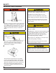
SAFETY Recognize Safety Information General Operational Safety Precautions Safety-Alert Symbol The Safety-Alert Symbol identifies important safety messages on equipment, safety signs, in manuals, or elsewhere. When you see this symbol, be alert to the possibility of personal injury or death. Follow the instructions in the safety message. Read and understand the operating instructions and become thoroughly familiar with the equipment and its controls before operating the dock leveler.
SAFETY Operational Safety Precautions Learn the safe way to operate this equipment. Read and understand the manufacturer's instructions. If you have any questions, ask your supervisor. Stay clear of dock leveling device when freight carrier is entering or leaving area. Chock/restrain all freight carriers. Never remove the wheel chocks until loading or unloading is finished and truck driver has been given permission to drive away.
SAFETY Do not use dock leveling device if freight carrier is too high or too low. Do not overload the dock leveling device. Do not operate any equipment while under the influence of alcohol or drugs. Do not leave equipment or material unattended on dock leveling device. 4111-0001 — Oct.
SAFETY Maintenance Safety Precautions ALWAYS disconnect electrical power source and ground wire before welding on dock leveler. DO NOT ground welding equipment to any hydraulic or electrical components of the dock leveler. Always ground to the dock leveler frame. Failure to follow these instructions may result in damage to dock leveler and/or serious personal injury or death. Hydraulic and electrical power must be OFF when servicing the equipment.
SAFETY Safety Decals Safety Decal on Leveler Frame Safety Decal on Platform Cylinder 4111-0001 — Oct.
SAFETY This page intentionally left blank 6 4111-0001 — Oct.
INTRODUCTION General Information Dock Leveler Stock Specifications PR dock levelers are available in the following sizes, weight capacities, and options: Width: PR 6 ft (1828.8 mm) 6-1/2 ft (1981.2 mm) 7 ft (2133.6 mm) Width: PR-XL 8 ft (2438.4 mm) 8-1/2 ft (2590.8 mm) Congratulations on your choice of a Poweramp dock leveler. This manual covers the PR series hydraulic dock leveler.
INTRODUCTION Component Identification E D B F A G C H M L K J A — Lip B — Platform C — Lip Cylinder(s)* D — Powerpack (Motor/Pump/Reservoir) E — Inspection Plate F — Logic Block G — Dual-Lanyard Pull Ring K — Maintenance Prop H — Platform Cylinder(s)* L — Lip Keepers (2 used) J — Main Frame M —Toe Guard (2 used) * Some models are equipped with multiple cylinders. 8 4111-0001 — Oct.
INSTALLATION Prepare Pit A C B D A—Distance (Pit Width) (Front and Rear) B— Distance (Dock Floor-to-Pit Floor) (All Four Corners) C— Distance (Pit Length) (Both Sides of Pit) D— Distance (Pit Corner-to-Corner) (Top, Bottom, and Both Sides) Before lowering the dock leveler into the pit, the following must be performed: Post safety warnings and barricade the work area at dock level and ground level to prevent unauthorized use of the dock leveler before installation has been completed.
INSTALLATION Prepare Dock Leveler A B A— Lifting Bracket (2 used) The dock leveler is heavy. Use a lifting device and chains with the appropriate lifting capacity and reach. Always use the lifting brackets provided with the unit whenever lowering or lifting a dock leveler into or out of a pit. B — Shipping Bands Poweramp dock levelers are designed with installation in mind. Each unit is shipped with lifting brackets (A) fastened to the platform side joists.
INSTALLATION 1. Remove any control panel and bumpers that may be banded to the frame of the dock leveler. DO NOT remove the shipping bands (B) around the platform lip and leveler frame at this time. IMPORTANT DO NOT overtighten the lifting bracket hardware. Overtightening can damage the weather seal, if equipped.
INSTALLATION Install Dock Leveler Shim Stacking Methods N A A P Q R C B D A— Distance (Leveler Frame Height) B— Shim Locations (Under Rear Vertical Supports) C— Shim Location (Under Maintenance Prop) (Standard Dock Leveler Only) D— Shim Locations (Under Lip Keepers) E— Dock Floor F— Rear Pit Curb Angle 12 G— String H— Rear Hinge Frame Angle J— Distance (Dock Floor-to-Pit Floor) K— Distance (Top of Shim Stack-to-Dock Floor) L— Shim Stack M— Dock Leveler Frame N — Pyramid (Preferred) P— Stepped (Acce
INSTALLATION NOTE: Poweramp dock levelers are designed with a nominal 1/2 in. (12.7 mm) shimming distance to allow for pit inconsistencies. 1. Determine height of shim stack (L) for each shim location (B) by performing the following: a. Measure leveler frame height distance (A). b. Measure dock floor-to-pit floor distance (J) at each shim location (B). Write down the dimensions obtained at each location. c. Subtract distance (A) from distance (J) to obtain the shim height. Repeat for each shim location.
INSTALLATION B A C C D D E F G A— Front of Dock Pit B— Dock Leveler Frame 3/8 in. (9.5 mm) 6 in. (152 mm) C— Side Pit Curb Angle D— Gap [3/4 in. (19 mm) Minimum] 8. With rear hinge frame angle (F) tight against rear pit curb angle (G), perform/check the following: • Pry between the platform and rear hinge frame angle at locations (E) to make sure rear edge of platform is parallel to the rear hinge frame angle (F).
INSTALLATION IMPORTANT DO NOT grind or weld if hydraulic fluid or other flammable liquid is present on the surface to be ground or welded. DO NOT grind or weld if uncontained hydraulic fluid or other flammable liquid is present. Stray sparks can ignite spills or leaks near the work area. Always clean up the oil leaks and spills before proceeding with grinding or welding. Always keep a fire extinguisher of the proper type nearby when grinding or welding.
INSTALLATION A D C B C E CleanPit Model Shown A— Platform Joists B— Shim Locations (Under Platform Cylinder Trunnions) C— T- Frame (CleanPit Only) D— Maintenance Prop (CleanPit Model Shown) E— Distance [8-1/2 in. (216 mm) Approx] (Center of Leveler to Center of Prop Mounting Plate) NOTE: For CleanPit models, proceed to step 17. 16. Standard models only: a. Install shims under maintenance prop (D) where prop attaches to leveler frame. Make sure prop is solidly shimmed. b.
INSTALLATION Closely follow the step-by-step instructions for installing the CleanPit maintenance prop. Failure to install the maintenance prop correctly may result in failure of prop during use, damage to equipment, and/or serious personal injury or death. Make sure the platform is properly supported in the raised position before entering the pit to finish weld the shims. Failure to do this may result in serious personal injury or death. 17. CleanPit models only: a.
INSTALLATION Install Control Panel and Wiring A The electrical power must be OFF prior to electrical installation. For maximum protection, use an OSHA approved locking device to lock out all power sources. Only the person installing the equipment should have the key to unlock the power source. Failure to follow these instructions may result in serious personal injury or death. B C DO NOT make any final electrical connections until all welding has been completed.
INSTALLATION Put New Dock Leveler Into Service 1. Disconnect the external lifting device and chains from the lifting brackets. 2. Check that the leveler is flush with the dock floor and that the platform lip contacts both lip keepers evenly. If an excessive transition exists between the dock floor and leveler and/or lip does not contact both lip keepers evenly, contact Poweramp Technical Services for further instructions. 3. Install the dock bumpers as required. 4. Turn the main electrical power ON.
INSTALLATION This page intentionally left blank 20 4111-0001 — Oct.
OPERATION Theory D B E A J F C K G L H M N P A — Lip B — Platform C — Lip Cylinder(s)* D — Electric Motor E — Inspection Plate F — Dual-Lanyard Pull Ring G — Logic Block H — Platform Cylinder(s)* The PR dock leveler uses hydraulic logic and one-button operation for ease of use. The dock leveler can be operated remotely using the RAISE button (J) on the control panel or operated locally using the dual-lanyard pull ring (F) located in a recess at the rear of the platform.
OPERATION Operating Instructions Stay clear of dock leveler when freight carrier is entering or leaving dock area. 12 in. (305 mm) DO NOT move or use the dock leveler if anyone is under or in front of leveler. 12 in. (305 mm) Keep hands and feet clear of pinch points. Avoid putting any part of your body near moving parts. Failure to follow these instructions may result in severe personal injury or death. Only trained personnel should operate the dock leveler.
OPERATION Operating Instructions—Continued Ramp Loading/Unloading Instructions NOTE: If end unloading is required, see End Loading/Unloading Instructions on page 24. For ramp loading or unloading, the PR dock leveler can be operated by using either the RAISE button on the control panel or the dual lanyard pull ring located in a recess at the rear of the platform. 1. Check to make sure truck/trailer is positioned squarely against dock bumpers. 2.
OPERATION Operating Instructions—Continued End Loading/Unloading Instructions NOTE: If ramp loading is required, see Ramp Loading/Unloading Instructions on page 23. End loading or unloading can be done with the dock at the cross-traffic position or below-dock position, depending on the height of the truck/trailer bed. B A A—ARTD Switch 1. Check to make sure truck/trailer is positioned squarely against dock bumpers. 2.
MAINTENANCE Service Dock Leveler Safely Side View F E A B D C A— Tagout Device B — Lockout Device C — Lockout Device When service under the dock leveler is required, always lock all electrical disconnects in the OFF position after raising the platform and engaging the maintenance prop. Failure to do this may result in serious personal injury or death. Always stand clear of the dock leveler lip when working in front of the dock leveler.
MAINTENANCE Periodic Maintenance C An inspection plate is provided in B the platform floor for ease of maintenance and pit inspection.
MAINTENANCE Regular maintenance must be performed on a weekly and quarterly schedule. P N Q Weekly Maintenance • Operate the dock leveler through the complete operating cycle to maintain lubrication. NOTE: To thoroughly inspect the platform hinge area, put the platform in the full below-dock position. M • Inspect the platform hinge and the lip hinge areas. The hinge areas must be kept free of dirt and debris. Build-up of foreign material in the hinge areas will cause abnormal operation.
MAINTENANCE This page intentionally left blank 28 4111-0001 — Oct.
ADJUSTMENTS Adjust Main Pressure Relief When service under the dock leveler is required, always lock all electrical disconnects in the OFF position after raising the platform and engaging the maintenance prop. Failure to do this may result in serious personal injury or death. B Always post safety warnings and barricade the work area at dock level and ground level to prevent unauthorized use of the dock leveler before maintenance is complete.
ADJUSTMENTS Adjust Cable Weight and Down Speed Control C A B G D H F E A— Speed Control Adjusting Screw B— Logic Block C—Valve Lever D— Cable E— Locking Pliers F— Cable Weight G—Steel Ball (2 used) H— Set Screw (2 used) Cable Weight Adjustment Down Speed Control Adjustment If the platform lip does not extend, or extends too soon, cable weight (F) may need adjustment. The cable weight is attached to cable (D) and is located underneath the platform, directly behind logic block (B).
ADJUSTMENTS Adjust Auto Return To Dock (ARTD) Adjust the ARTD as Follows: D E F C When service under the dock leveler is required, always lock all electrical disconnects in the OFF position after raising the platform and engaging the maintenance prop. Failure to do this may result in serious personal injury or death.
ADJUSTMENTS IMPORTANT 6. Turn ON electrical power to the dock leveler. Anytime proximity switch and target are adjusted, always check for interference between target and switch before operating the leveler. Damage to switch will occur if the target contacts the switch. 7. Disengage the maintenance prop. The maximum torque for proximity switch lock nuts is 27 N•m (29 lb-ft). Damage to switch will occur if maximum torque is exceeded. 9.
ADJUSTMENTS Full Below-Dock Position Lip Fully Extended Position Lip Keeper Whenever the platform lip is at the fully extended position, the following conditions will exist for a normally operating ARTD: • Target not in the sensing area of proximity switch. Whenever the platform lip is at the full below-dock position, the following conditions will exist for a normally operating ARTD: • Proximity switch OFF (open) (no signal sent to the control panel). • Proximity switch indicator light is OFF.
ADJUSTMENTS This page intentionally left blank 34 4111-0001 — Oct.
TROUBLESHOOTING Troubleshooting When service under the dock leveler is required, always lock all electrical disconnects in the OFF position after raising the platform and engaging the maintenance prop. Failure to do this may result in serious personal injury or death. Always post safety warnings and barricade the work area at dock level and ground level to prevent unauthorized use of the dock leveler before maintenance is complete. Failure to do this may result in serious personal injury or death.
TROUBLESHOOTING Symptom Three-phase units only: Platform does not rise. Motor hums, but does not run. Possible Cause Solution No voltage is present on one line. Check for blown fuses at branch circuit disconnect. Replace fuse. Determine cause of blown fuse. NOTE: A motor that is missing voltage on one line is said to be single-phased. Check motor starter as follows: 1. Disconnect wires at load side of starter. 2. Energize the starter. 3. Measure line-to-line voltage at line side of starter. 4.
TROUBLESHOOTING Symptom Platform does not rise. Pump operates in pressure relief mode. Possible Cause Solution Heavy object(s) on platform. Remove object(s) from platform. NOTE: For safety reasons, the dock leveler is designed to lift only the platform’s own weight. Dock leveler binds. Check for visible obstructions that could cause binding. Remove obstructions. If no obstructions found, call Poweramp Technical Services. See inside back cover for phone number and address. Pressure relief set too low.
TROUBLESHOOTING Symptom Possible Cause Solution Platform does not rise to Low hydraulic fluid. full height. Add fluid as needed. See Periodic Maintenance in the Maintenance section. Platform DOES rise to full height, but lip DOES NOT extend or extend fully. Low hydraulic fluid. Add fluid as needed. See Periodic Maintenance in the Maintenance section. Logic block (valve) lever cable weight too low on cable. Adjust cable weight.
PARTS Controls B A D C Item Quantity Part Number A B 1 1 C 1 D 1 0961-0085 * 9511-0004 9512-0429 0961-0014 Description Proximity Switch with Harness (ARTD Feature Only) Push Button Controller J-Box, Standard (4 x 4 in. Metal Box) J-Box, Cold Weather (5 x 5 in. Plastic Box) Microswitch with Harness (Dual Lanyard Feature Only) * Provide dock leveler serial number, voltage, phase, and options when calling or faxing controller orders. 4111-0001 — Oct.
PARTS Frame and Platform A B Y X W S C V U T P R D Q N M J E K L H F G Z AA 40 4111-0001 — Oct.
PARTS Frame and Platform Item Quantity Part Number A 1 0595-____1 Lip, Welded Assembly B 1 7823-____2 Plate, Inspection C D 1 1 9515-____1 9202-0003 Platform, Welded Assembly 6’ x 1-1/8” Pin, Lip Hinge, 2002 and Older 1 9202-0014 6-1/2’ x 1-1/8” Pin, Lip Hinge, 2002 and Older 1 9202-0006 7’ x 1-1/8” Pin, Lip Hinge, 2002 and Older 1 9202-0050 6’ x 1” Pin, Lip Hinge, 2003 and Newer Pin 1 1 9202-0051 9202-0052 6-1/2’ x 1” Pin, Lip Hinge, 2003 and Newer Pin 7’ x 1” Pin, Lip Hinge, 2003
PARTS Hydraulic Components G B F Lip Hose A H D E C J Pressure Hose AL AK AJ K AH AG AB AM Z L AA AC AF AD Y AE X N M P Return Hose W Q R V U Hoist Hose T 42 S 4111-0001 — Oct.
PARTS Hydraulic Components Item Quantity Part Number A B C D 1 1 1 1 E 1 F G H J K L M N P Q R S 1 2 1 1 1 2 2 1 2 2 4 2 1 1 1 1 1 1 1 2 2 1 1 1 2 1 1 1 6 1 1 4 1 1 0522-0005 2101-0045 0522-0156 0521-0005 0525-0086 0525-0087 9202-0004 2101-0049 9301-0111 9904-____1 9904-____1 2101-0015 2101-0039 9575-____3 2101-0050 9202-0005 2101-0009 7942-0006 0525-0043 0525-0044 0525-0045 0525-0046 9301-0120 9904-____1 9904-____1 2101-0040 2101-0060 9455-____2 0522-0002 0521-0007 2101-0011 9395-____3 0521-0016 0
PARTS Platform Cylinder Repair Parts A B C D E F G H J Item Quantity Part Number A B C D E F G 1 1 1 1 1 1 1 H 1 J 1 1 1 0522-0120 0521-0104 0521-0008 0521-0009 0521-0103 0521-0105 0521-0013 0525-0043 0525-0044 1751-0138 0525-0013 0525-0048 Description Gland Rod Step Seal O-Ring Backup Ring Wear Ring (Slydring) Excluder Plus Seal Retaining Ring Cylinder, Platform, 15-1/2 in. (394 mm) Barrel Length Cylinder, Platform, 17-1/2 in.
PARTS Lip Cylinder Repair Parts B A C E F G H J D K Item Quantity Part Number A B C D E F G H J 1 1 1 1 1 1 1 1 1 K 1 1 0524-0077 0521-0109 0521-0110 0524-0051 0521-0050 0522-0091 2101-0085 0524-0068 0521-0004 0525-0086 0525-0087 0525-0014 1 0525-0059 Description Cylinder Barrel Assembly Wear Ring Piston Seal, 3-Piece Piston Assembly Spring Spring Guide Flat Washer, 2-1/4 in. OD x 1-3/16 in. ID x 9/64 in. Thk. Cylinder Head Retaining Ring Lip Cylinder, 13-3/4 in.
PARTS Logic Block Assembly S T AA B C U D Z W X Y R A D L E V J F G H J Q P N M L K 46 PR 4111-0001 — September 2002
PARTS Logic Block Assembly Logic Block and Lever Arm Item Quantity A 1 B 1 Part Number 9574-0001 9574-0002 5455-0001 5455-0004 Description Spool Valve, Logic Block, Standard Spool Valve, Logic Block, Cold Weather Lever Arm, Standard Lever Arm, Cold Weather Logic Block Cable Assembly Item C D E F G H Quantity 1 2 1 1 2 2 1 Part Number 7955-0001 2101-0059 9572-0004 8102-0001 9552-0001 2101-0032 5265-0002 Description Cable Subassembly, Logic Block Washer, 1/4 in.
PARTS Power Pack Assembly J L K M H D G E C F AC AB N P Q B AA R Z S Y A W T X U T V 48 4111-0001 — Oct.
PARTS Power Pack Assembly Item Quantity Part Number A B C D E F 2 2 1 1 1 2 1 4 1 1 1 1 1 1 1 1 1 1 1 1 2 1 1 1 1 1 1 2 2 2 1 2101-0039 9301-0029 9302-0014 9301-0199 9301-0027 9302-0012 9301-____ 1 2101-0016 9301-0028 9303-0002 9302-0017 9904-0001 0521-0017 0521-0007 3411-____ 2 0521-0015 0521-0014 9301-0024 9302-0009 9303-0003 9301-0014 9301-0015 9301-0016 0521-0016 9301-0009 9301-0082 9301-0008 9301-0003 9301-0004 2101-0063 9395-____ 1 G H J K L M N P Q R S T U V W X Y Z AA AB AC 1 2 Description N
PARTS Weather Seal, Rubber Style A G B D F C E Item Quantity Part Number A B C 3 1 1 1 1 AR AR 1 1 1 0192-____* 0192-____* 0192-____* 0192-____* 0192-____* 2101-0039 2101-0011 0192-____* 0195-____* 0195-____* D E F G Description Foam Seal, Rear Hinge Rubber Seal, Rear (Flat, Bend to Fit) Rubber Seal, Left Side Neoprene Seal, Short Vertical, Right Neoprene Seal, Short Vertical, Left Nylon Lock Nut, 5/16-18 UNC (Side Weather Seal w/o Toe-Guard) Cap Screw, 5/16-18 UNC x 1 in.
PARTS Weather Seal, Brush Style F E B D A C Item A B C D E F Quantity Part Number 1 1 1 1 1 AR AR 1 1 1 1 1 1 1 1 1 1 0192-____* 0192-____* 0192-____* 0192-____* 0192-____* 2101-0039 2101-0011 0192-____* 0192-____* 0192-____* 0195-____* 0195-____* 0195-____* 0195-____* 0195-____* 0195-____* 0195-0044 Description Brush Seal and Track, Left Side, 1 in. (25 mm) Brush Seal and Track, Left Side, 1-1/2 in. (38 mm) Brush Seal and Track, Left Side, 2 in.
PARTS This page intentionally left blank 52 4111-0001 — Oct.
MISCELLANEOUS Customer Information A NOTE: Refer to illustration for left/right orientation of dock leveler. The model/serial number decal (A) is located on the right platform joist near the front (lip) of dock leveler. When you receive your PR dock leveler, write down the dock leveler model and serial number in the form provided. This will help ensure safe keeping of the numbers in the event the model/serial number decal (A) becomes lost or damaged. Also, write down Systems, Inc.
POWERAMP WARRANTY PR SERIES LEVELER Systems, Inc., guarantees the materials, components, and workmanship in your Poweramp dock leveler to be of the highest quality and to be free of defects in material and workmanship for a period of Seven (7) Years from date of shipment, specifically the deck section, lip section, frame, rear hinge, front hinge. Systems, Inc., further guarantees the hydraulic components on all Poweramp dock levelers for a period of Seven (7) Years from date of shipment.