PS-AWB101T PS-AWB121T AMPLIFIED THIN SUBWOOFER AIR SUSPENSION SYSTEM Application & Enclosure Guide Please read through this manual to familiarize yourself with your new subwoofer. Should your PowerBass Autosound Subwoofer System ever require service, you will need to have the original dated receipt.
Thank you and Congratulations Congratulations on your purchase of a PowerBass Autosound speaker system. You now own a speaker of uncompromising design and engineering from a factory that truly believes in the relentless pursuit of perfection. Incorporating the highest quality parts and state-of-the-art materials, these speakers display the ultimate balance between high fidelity, performance and long-lasting reliability. ···® ••• ••• At PowerBass USA, Inc.
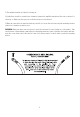
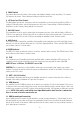
POWERBASS AMPLIFIED BASS SYSTEM FEATURES Built-in High Powered Amplifier: Contains a high power Class A/B monaural amplifier complete with chassis mounted adjustable Gain, Low Pass Filter and Bass Eq controls for sonic integration into most existing factory or aftermarket car stereo systems and engineered perfectly to power the subwoofer. Heavy-duty Box Design: This enclosure is constructed from non-resonant 5/8” panels that have been glued, braced and sealed.
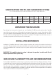
SPECIFICATIONS FOR PS-AWB SUBWOOFER SYSTEM (Due to Constant Improvements, Specifications and Parameters are subject to change without notice.) Model Size System Impedance Frequency Response Sensitivity 1W/1M Magnet Size Voice Coil Dia. Amp Power RMS/Peak PS-AWB121T Single 12” 4-ohm 36Hz-250Hz 91dB 45 oz. 2.0” 200W/400W 91dB 40 oz. 2.
1) The amplifier heatsink end should be facing out. 2) Ideally there should be several inches clearance between the amplifier heatsink and the seat or surface it is backed up to. Make sure the open port beside the woofer is not obstructed. 3) When all connections are made the final step should be to secure the enclosure using the mounting brackets provided so it remains securely in place. WARNING: Make sure where ever you choose to place the enclosure it’s a dry location on a solid surface.
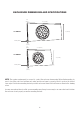
ENCLOSURE DIMENSIONS AND SPECIFICATIONS 3.75” (95mm) 30.3” (770mm) PS-AWB121T Mounting Bracket 14” (356mm) ------- ~ "' 5.75” (146mm) 3.5” (89mm) 21.5” (546mm) PS-AWB101T 13” (330mm) Mounting Bracket ------- ~ ...__, - 6.75” (171mm) NOTE: The speaker system must be secured to protect the enclosure from moving. Before final mounting, be sure to check the sound one last time and make sure the enclosure is properly placed to produce the desired bass output.
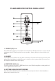
PS-AWB AMPLIFER CONTROL PANEL LAYOUT 0 0 4.}----- 0 g}--------0 ~ FUSE GND 0 REM BATT+ 10,,---------<.......... , 0 Fig.2 1. LOW INPUT (RCA) Jacks These RCA style input jacks are for use with source units that have RCA line level inputs. A source unit with a minimum output of 100mV is required for proper operation. However, this input can accept levels up to 6Vrms. 2.
5. PHASE Switch This switch will reverse the phase of the speaker output without having to touch any wiring. 0 is normal. 180 reverses the output. Select whichever setting provides the most bass. 6. LPF (Low Pass Filter) Control This filter allows the low pass of frequency and has an adjustable crossover point from 50Hz to 200Hz. A setting of 50Hz will produce only the low frequencies (deep bass). A max setting of 200Hz will allow the amplifier to produce a more punchy (higher) bass response. 7.
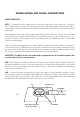
POWER WIRING AND SIGNAL CONNECTIONS POWER CONNECTION BATT+ The amplifier should be wired directly to the vehicle battery using a 8ga power cable. Start at the vehicle battery and run the power cable through the vehicle’s firewall using grommets to the amplifier’s BATT + screw terminal. If factory grommets are not available install grommets yourself to protect the cable from sharp metal edges. Avoid running the power cable over the engine components and near heater cores.
INPUT SIGNAL (CHOOSING THE HIGH OR LOW INPUTS) The PS-AWB amplifer control panel input signal connects to the head unit’s High Level (speaker wire) output OR Low Level (RCA) output—provided the radio is so equipped with Line Out. A dedicated subwoofer or low level signal will deliver the best performance. If unavailable use the high level inputs, as will be the case with most factory head units.
Fig.
Low Level Input and RCA Interconnect Wiring (fig 5) For radios that have RCA line outputs. You will need to connect the low-level RCA style inputs from the PSAWB to the line-outputs from the radio (source) via an RCA interconnect commonly called a “stereo patch cord”. Choose the correct length and style of RCA interconnects for your needs.
Fig.5 Low Level Connections CAR RADIO 0 r----.1 I I I L----7 0 I I I O l__ (i) (i)__ J :l1I!JJ' -c::.- ·a:J- --~ = 0 0 ~ •ta' ~-, -..
SET UP ADJUSTMENTS Your PS-AWB enclosure uses several controls to provide sonic integration with virtually any vehicles unique acoustic properties. Please read the following section carefully to familiarize yourself with the function of each control. The following adjustment sequence is recommended to properly tune your PS-AWB enclosure. By first adjusting the GAIN, the LPF, then the PHASE switch, followed by the BASS EQ (in this order) will give you the best results. GAIN MIN MAX Fig.
SWITCH POSITION PHASE Fig.8 PHASE Switch Setting the PHASE switch Start with the PHASE switch set at 0˚ and play a favorite music track that contains some solid bass (make sure the BASS EQ control is set at the 12 o’clock position). Then flip the switch to 180˚ and listen to the same musical track again. Choose the setting that provides the best bass response according to your taste. BASS EQ □ dB 12dB Fig.
Fig.10 Connection with RJ45 Jack Remote Level Controller Your PowerBass PS-AWB enclosure includes a wired Remote Level Subwoofer control module. It uses standard telephone wire and telephone RJ45 connectors. To connect the Remote Subwoofer Gain control to the amplified enclosure, simply insert one end of the telephone plug into the REMOTE gain port. Plug the other end into the back of the remote module. Mount the module within easy reach or under your dash.
TROUBLESHOOTING TIPS Problem Solution Power LED not ON With a Volt OHM Meter (VOM) check: • +12 Volt power terminal (should read +12 to +16VDC • Remote turn-on terminal (should read +12 to +16VDC) • Ground Terminal Power LED lights RED, no output • • • • Check RCA connections Test speaker outputs with known good speaker Substitute known good Source Unit Check for signal on the RCA cable with VOM in AC position Power LED lights RED, but volume reduces automatically.
WE WANT YOU LISTENING FOR A LIFETIME Dear Customer, Selecting fine audio equipment such as the speakers you’ve just purchased is only the start of your musical enjoyment. Now it’s time to consider how you can maximize the fun and excitement your equipment offers. PowerBass and the Consumer Electronics Association (CEA) want you to get the most out of your equipment by playing at a safe level.
POWERBASS AUTOSOUND LIMITED WARRANTY POLICY PowerBass USA, Inc. offers limited warranty on PowerBass products under normal use on the following terms: PowerBass Autosound Speakers are to be free of defects in material and workmanship for a period of one (1) year. This warranty applies only to PowerBass products sold to consumers by Authorized PowerBass Dealers in the United States of America.
···® ••• ••• PowerBass Autosound – A division of PowerBass USA, Inc. 2133 S. Green Privado – Ontario, CA 91761 Tel. (909) 923-3868 – Fax (909) 923-8048 www.powerbassusa.