
Owner's Manual


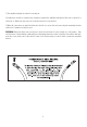
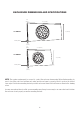
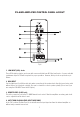
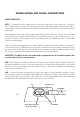

Table Of Contents
5. PHASE Switch
This switch will reverse the phase of the speaker output without having to touch any wiring. 0 is normal.
180 reverses the output. Select whichever setting provides the most bass.
6. LPF (Low Pass Filter) Control
This filter allows the low pass of frequency and has an adjustable crossover point from 50Hz to 200Hz. A
setting of 50Hz will produce only the low frequencies (deep bass). A max setting of 200Hz will allow the
amplifier to produce a more punchy (higher) bass response.
7. BASS EQ Control
This equalization circuit is used to enhance the low frequency response of the vehicles interior. With up to
12dB of boost centered at 45Hz the Bass EQ can be adjusted to meet your personal taste. Please note that
by boosting the Bass EQ to its full +12dB you are asking the amplifier to work 10 times harder!
8. GAIN Control
This control is used to match the sensitivity of the amplifier to the particular source unit (radio) that you are
using up to 6 volts in Low Input Mode and up to 10 volts in High Input Mode. Please note the GAIN control is
not a volume control, it is a level match.
9. POWER Indicator
This RED L.E.D. lights up when the power is on and the system is wired correctly. The LED will shut off if the
unit is either in protect mode or powered down.
10. FUSE
For convenience most PowerBass AutoSound amplifiers utilize common automotive ATC type fuses. For
continued protection in the event that a fuse blows, replace the fuse only with the same value. PS-
AWB110T uses a 15A fuse, PS-AWB112T uses a 20A
CAUTION: These power fuses on the amplifier chassis are for protecting the amp against over current
situation. To protect the vehicles electrical system, an additional fuse should be used within 18-inches of the
battery on the 12V+ cable.
11. BATT+ (12 Volt Positive)
This terminal is the main power input for the amplifier and must be connected directly to the positive (+)
terminal of the battery. A minimum of 10ga cable is required.
12. REM (Remote)
The amplifier in your PS-AWB enclosure can be turned on by applying 12 volts to this terminal. This can be
on the rear of the source unit (radio) in the form of an electric antenna output or remote output. If this is not
available you can wire up to the ACC position on the ignition key switch. An 18ga wire is sufficient to run the
remote. NOTE: If this unit is used in High Level Input Mode and the Auto Turn-On is switched on,
there is no need to hook the remote wire up.
13. GND (Ground Input Connection)
A good quality ground is required for the amplifier to operate a peak performance. A short length of cable
the same gauge as your power cable (8ga is recommended) should be used to attach the ground terminal
directly to the chassis of the vehicle. Make sure that all of the paint is sanded or scraped away to ensure a
good quality ground connection.
8