
Owner's Manual


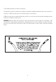
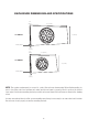
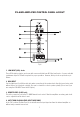
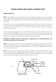

Table Of Contents

POWER WIRING AND SIGNAL CONNECTIONS
POWER CONNECTION
BATT+ The amplifier should be wired directly to the vehicle battery using a 8ga power cable. Start at the
vehicle battery and run the power cable through the vehicle’s firewall using grommets to the amplifier’s BATT +
screw terminal. If factory grommets are not available install grommets yourself to protect the cable from sharp
metal edges.
Avoid running the power cable over the engine components and near heater cores. The use of an in-line fuse
or circuit breaker is a must, this will prevent the risk of potential fire caused by a short in the power cable. Con-
nect the fuse holder or circuit breaker as close to the battery positive (+) terminal as possible (no farther than
18-inches from the battery).
The fuse or breaker amperage should be no greater than the fuse rating found on the amplifier control panel lo-
cated on the side of the PS-AWB enclosure. You can now connect the cable to the battery, but remember to leave
the fuse out or the circuit breaker “off” until the other cable connections are made. It is highly recommended that
the cable end connecting to the amplifier is terminated with a spade or ring terminal.
IMPORTANT—You MUST install a fuse holder with an appropriate fuse in line with the power cable
no further than 18-inches from the battery.
REM Run 18ga wire (not included) to the radio power antenna lead or remote output. This wire is responsible
for turning the amplifier on and off. If the source unit (radio) is not equipped with a Remote lead you can connect
this wire to an accessory or ignition point at the vehicle fuse block. In this type of installation, the amplifier will
be on whenever the ignition is on.
GND A cable of the same size (gauge) as the power cable should be used to ground the amplifier. Connect
the ground wire from the screw terminal marked GND on the amplifier control panel to the nearest bare-metal
surface on the vehicle. Keep the length of the ground cable to an absolute minimum using a spade terminal at
the amplifier end and ring terminal as shown in below at the chassis end (Fig 3).
Bolt
Note: Remove any paint
below ring connector
Star Washer
Ring Connector
Ground Wire
9
Fig.3