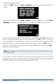
Instruction Manual PowErBox Cockpit PowErBox CompEtition PowErBox ProfEssionAl
Dear customer, We are delighted that you have decided to purchase a power supply unit from PowerBox-Systems. We hope you have many hours of pleasure and great success with your new PowerBox. 1. PRODUCT DESCRIPTION The PowerBox Competition, Cockpit and Professional have undergone constant development since their introduction in 2009. For example, the menu system has been improved, and new functions such as telemetry and the door sequencer assistant have been added.
FEATURES: Integral high-resolution graphic OLED screen with 128 x 64 pixels Particularly user-friendly menu-based programming using the SensorSwitch Door sequencer: six freely programmable outputs with setup assistant Channel lock when undercarriage is retracted 11 channels inclusive one channel for the doorsequencer in the Cockpit Version 12 channels in the Competition version 8 channels in the Professional version Signal amplification and interference suppres
2.
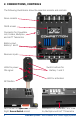
3. FIRST STEPS, THE UNIT IN USE: In the following instructions we do not differentiate between the PowerBox Cockpit, Competition and Professional, since the method of programming the three units is absolutely identical. The only difference is that the PowerBox Cockpit includes the door sequencer function. 3.1 CONNECTIONS Plug the batteries into the MPX connectors on the backer with correct polarity. We recommend PowerPak 2.5 X2 or 5.0 X2.
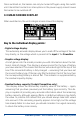
Once switched on, the backer can only be turned off again using the switch unit. Intermittent contacts or interruptions in the power supply cannot cause the backer to be switched off. 3.3 MAIN SCREEN DISPLAY When switched on, the unit’s integral screen shows this display: Key to the individual display points: - Digital voltage display: This extremely accurate display allows you to read off the voltage of the battery directly, i.e. the voltage which is present at the input of the PowerBox.
- Graphic indicator of battery charge state: This display is set to match the capacity you previously entered for the batteries connected to the backer. Assuming that the battery is of good quality, this means: if the bar only reaches the half-way point, then the battery is still half-full. - Operating time: This figure shows the elapsed time since the last RESET. It is important always to carry out a RESET after each battery charge process.
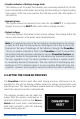
3.5 BASIC SETTINGS The PowerBox Cockpit, Competition and Professional feature a new kind of graphic OLED screen, intended to do away with old-fashioned programming methods based on flashing LED codes, morse code beeps or mechanical jumpers. The screen provides the basis for an extremely user-friendly control system, and eliminates the need for a supplementary setup unit or programming device.
- Switch both batteries on. - Press the SET button and hold it pressed in until the following display appears: - Press button II until the cursor (hollow circular ring) lines up with Power Manager, then press the SET button. The following display now appears: I f you wish to change one of the settings, use buttons I and II to move the cursor to the appropriate menu point, then press the SET button to select it (cursor changes to a solid disc). You can now alter the value using buttons I and II.
Key to the individual menu points: - Chemistry: this is where you set the battery type. Three different types of battery are available: • • • • Two-cell LiPo Two-cell LiIon Five-cell NiMH Two-cell LiFe - Capacity: you can enter the nominal capacity of your batteries at this point. - Output voltage: you can select the output voltage to 7.4 V or 5.9 V CAUTION: if you intend to select the 7.4 V output voltage, please ensure before you make the change that all the consumer units connected to the unit, i.e.
4. SERVO MATCH FUNCTION The Servo-Match function provides the facility for adjusting the centre position and end-points of the servos connected to the backer. If you have a model aircraft with more than one servo per control surface, this makes it possible to set up multiple servos to move to identical positions at identical times.
The following examples illustrate the correct procedure for the Servo-Match function: a) Fine-tuning multiple servos to operate on a single control surface; in this case the aileron of the right-hand wing. - Disconnect the linkages to the - as yet unmatched - servos, to avoid them being subjected to severe forces during the adjustment procedure.
b) Reversing an output when servos are installed in a “mirror-image” arrangement: in this case left and right landing flaps. - Disconnect the linkage to the left-hand landing flap, to avoid the servo being subjected to severe forces during the adjustment procedure. - Connect right landing flap to Output D, Servo 1 -F irst set up the right-hand landing flap servo in mechanical terms, using the transmitter; continue adjusting until the centre point and the maximum end-points are exactly as required.
5. SETTING UP THE DOOR SEQUENCER Select the SEQUENCER point at the main menu; this takes you to the following screen display: The SETUP ASSISTANT is a function in the Cockpit which has been included since software version V15; it makes the task of programming the actual door sequencer function considerably easier.
that your retract switch works in the wrong “sense” (direction), correct it by reversing that output at the transmitter. Press the SET button again to leave this function, and move the cursor to OK.
Mode 3: Extend undercarriage: Open nosewheel doors Open main wheel doors doors extend nosewheel close nosewheel doors extend main undercarriage close main wheel Retract undercarriage: Open nosewheel doors Open main wheel doors doors retract nosewheel close nosewheel doors retract main undercarriage close main wheel Move the cursor to the appropriate mode, and press the SET button to confirm your choice. Select OK to move on to the next screen display: Connect your retract system valve to output 4.
The undercarriage should now retract. If not, hold button I pressed in until the valve is triggered, and the undercarriage retracts. Press the SET button to move on to the next stage of the procedure. Connect the nosewheel door servo to output 1. Press the SET button to close the nosewheel door; repeat the procedure in the next setup screen to open the door.
Note: if you are only using one valve for all the wheel doors, you can bypass the last five points by selecting OK. All the settings are now complete, and you will see one final safety query: Move your transmitter switch to the “gear down” position. It will now take a few moments for the Assistant to create the necessary tasks, and move the doors to the correct position without any fouling or jamming.
In spite of the vast scope of these facilities, the sequencer is simple and user-friendly to set up, as the screen and menu system guide you through the procedure. The sequencer software also features supplementary programming aids. Once you understand the principle, the system can easily be programmed without recourse to the manual. We always recommend that you start the setup procedure using the Setup ASSISTANT.
Intelligent programming aid: If you wish to set up multiple tasks in order to move the wheel doors to several positions, it should be obvious that the new task’s initial positional value and start time are determined by the previous position and time for the servo concerned. This is carried out automatically, helping to speed up the programming procedure, and eliminates the need for you to note down the servo’s previous position and stop time.
The positional values vary according to your linkages, and must be adjusted to suit your individual model. Clearly it is important to avoid your wheel doors jamming (striking their mechanical end-stops). The timing values shown here should also be set to suit your requirements. The task numbering does not need to coincide with the timed sequence; for example, Task 5 could be set to run before Task 2. Our example clearly shows how the function is built up.
6. CHANNEL LOCK WHEN UNDERCARRIAGE IS RETRACTED The PowerBox Cockpit’s door sequencer also features one last unique function: it is now possible to switch a channel off when the undercarriage is retracted. The purpose of this feature is to prevent the retracted nosewheel moving inside the fuselage when the pilot gives a rudder command, as this may cause the mechanical system to jam. The function can be found under GEAR UP – OUTPUT OFF in the Door Sequencer menu.
8. TELEMETRY The PowerBox Cockpit, Competition and Professional makes battery data available as telemetry information which can be exploited by various makes of radio control system. The unit supports the following makes of equipment, and other systems will gradually be introduced as updates become available: - PowerBox CORE P²BUS Connect the PowerBox telemetry output to the receiver’s P²BUS input using a standard commercial Uni patch-lead.
- HoTT Connect the backer’s telemetry output to the receiver’s Sensor input using a standard commercial Uni patch-lead. Select the “Electric Air Module” in your transmitter’s telemetry menu. The voltage of both batteries, and the residual capacity of the weaker battery, can now be viewed on the transmitter’s screen. 9. RESET, UPDATE, SAVE AND RESTORE The PowerBox Cockpit, Competition and Professional offers numerous facilities for resetting individual ranges without affecting other settings.
10. REGULATOR ERROR MESSAGE The PowerBox Cockpit, Competition and Professional constantly checks both voltage regulators independently of each other. If a fault should occur in one of these regulators, this warning will appear on the screen: There are three possible causes for this warning: - One or both regulators is generating insufficient output voltage or none at all. This could mean that you are flying with only one regulator functioning, and for reasons of safety this is not permissible.
11. SPECIFICATION Operating voltage: 4.0 Volt to 9.0 Volt Power supply: 2 x two-cell LiPo/LiIon battery, 7.4 Volt 2 x five-cell NiCd / NiMH batteries, 2 x two-cell LiFePo batteries (A123) Current drain: switched on – approx. 125 mA switched off – approx. 33 µA Dropout voltage: approx. 0.25 V Max. receiver and servo current: 2 x 10 A (stabilised) according to cooling Peak 2 x 20 A Servo signal resolution: 0.
12. DIMENSIONS www.powerbox-systems.
13. SET CONTENTS - PowerBox Cockpit / Competition / Professional - 8, 11 or 12 patch-leads - SensorSwitch - 4 rubber grommets and brass spacer sleeves, factory-fitted - 4 retaining screws - Operating instructions 14. SERVICE NOTE We are anxious to offer good service to our customers, and to this end we have set up a Support Forum which deals with all queries concerning our products. This relieves us of a great deal of work, as it eliminates the need to answer frequently asked questions time and again.
The guarantee does not cover damage caused by incorrect usage, e.g. reverse polarity, excessive vibration, excessive voltage, damp, fuel, and shortcircuits. The same applies to defects due to severe wear. We accept no liability for transit damage or loss of your shipment.
01/2021 PowerBox-Systems GmbH Ludwig-Auer-Straße 5 D-86609 Donauwoerth Germany +49-906-99 99 9-200 +49-906-99 99 9-209 www.powerbox-systems.