40/16 Operating Instructions Double voltage stabilisation with linear regulation and double battery monitor, double signal amplification for each channel, twin electronic safety switches (SensorSwitches) petty patent no.: 203 13 420.
POWER BOX Evolution 40/16 Dear customer, We are delighted that you have decided to purchase the PowerBox 40/16 Evolution from our range. Your valuable model aircraft can now be fitted with one of the most capable battery backers available, enabling you to couple two batteries (battery backer) and also constantly monitor the voltage of the two batteries of your choice (NC, NiMH or LiPo). The minimum value of the battery voltage curves is stored, and can be called up again after each flight.
POWER BOX Evolution 40/16 1. History of PowerBox Systems voltage-stabilised battery backers TOC 2002, Las Vegas: this is where the development of the first voltage-stabilised power supply systems for model aircraft began. In October 2002 Sebastiano Silvestri took part in the Tournament of Champions at Las Vegas; he was the first TOC participant to have a type of receiving system power supply installed in his Katana which had never been seen before.
POWER BOX Evolution 40/16 This is in direct contrast with other manufacturers’ products which contain no duplicated components - as required for a truly secure system - even though they are powered by two batteries. You have selected a product which offers genuine duplication of systems (system redundancy) in the interests of your safety.
POWER BOX Evolution 40/16 If both batteries are in good condition, both contribute to the receiving system’s power supply. This means that each battery only bears half the total load, and both are recharged to the same level during the charge process. This arrangement avoids premature damage to your battery cells, and extends the useful life of your receiver packs significantly.
POWER BOX Evolution 40/16 You should check before every flight - by “stirring the sticks” - that the voltage of both batteries remains stable. If the batteries in your model are too “weedy” for the application, i.e. of inadequate capacity, this check will immediately show up the shortcoming.
POWER BOX Evolution 40/16 You can now move the two micro-DIP switches to the opposite end-point using a small, pointed screwdriver. Caution: very little force is required for this, and you can easily damage the switches if you use too coarse an instrument. Now connect the batteries you wish to use to the PowerBox. The PowerBox 40/16 Evolution is equipped with five stabilised two-way signal amplifiers, i.e. a separate amplifier for each channel.
POWER BOX Evolution 40/16 This measure is necessary because there are servos available on the market fitted with electronic circuitry which does not prevent reverse voltage. Certain receiver types are also not protected against this potential problem. The design of our PowerBoxes ensures that you can use any type of servo and receiving system.
POWER BOX Evolution 40/16 4. Specification Operating voltage: Power supply: Current drain: Voltage drop: Max. receiver current: Servo sockets: Max. continuous current: Temperature range: Dimensions: Weight: SensorSwitch: 5. 4.0 to 9.0 Volts Two 5-cell NiCd or NiMH batteries Two 2-cell LiPo batteries, 7.4 Volt approx. 70 mA approx. 0.25 V 2 x 10 A (stabilised) 16 sockets, 5 channels 20 A -10°C to +75°C 91 x 65 x 19 mm (incl.
POWER BOX Evolution 40/16 Power is fed to the receiver and all the other servos via all five servo leads, which should be connected to the channel sockets of your receiver; the socket marked “B” (battery) should be left unused. All connecting leads at the receiver can be connected in any sequence. The only requirement is that the assignment number at the PowerBox input must be identical to the channel number of the PowerBox output; these are therefore numbered from 1 to 5. 6.
POWER BOX Evolution 40/16 Charging these batteries is as simple as charging a mobile phone! Naturally, each battery set includes a practical mount and accessories. Of course, it is possible to connect two separate receivers to this battery backer. If you wish to do this be sure to observe the information supplied by your RC manufacturer concerning the use of two receivers in a model, otherwise there may be problems with interaction between the two units (minimum physical separation 20 cm).
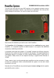
POWER BOX Evolution 40/16 Ribbon cable for connection to battery backer Retaining screw SET button for activating a switching process Red LED, indicates active state Switch button, Battery 1 Two green LEDs, indicate the switched state Switch button, Battery 2 Pressing both switch buttons simultaneously activates a read-out of the minimum value memory Retaining screw The SET button is slightly recessed, and its purpose is to prepare and carry out a switching process.
POWER BOX Evolution 40/16 When the unit is switched off, the “Standby” circuit of the electronic switches draws an idle current of around 5μA. This equates to a fraction of the self-discharge rate of normal batteries. The ribbon cable attached to the SensorSwitch should be plugged into the red multi-pin socket on the right-hand side of the backer.
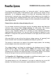
POWER BOX Evolution 40/16 Please don’t just throw away the inner packaging, as it includes a template for marking the switch aperture. Cut or saw clear of the marked line, as shown in the photo. Even though our product is very well protected >from the effects of vibration, the switch should always be mounted in a part of the model relatively low in vibration. Please note that the GRP fuselage sides of a large power model are not suitable, as they are always subject to considerable vibration.
POWER BOX Evolution 40/16 The battery backer fulfils the EMV protection requirements, entitling it to bear the CE symbol. However, please note that the unit is designed and approved solely for use in modelling applications, and may only be used in radio-controlled models. The unit should only be used with a Direct Current (D.C.) power supply corresponding to an NC or NiMH battery consisting of five cells, or a two-cell LiPo pack. It must never be connected to a mains PSU! 8.
POWER BOX Evolution 40/16 We wish you every success using your new battery backer, and hope you have loads of fun with it.
PowerBox-Systems GmbH Ludwig-Auer-Strasse 5 D-86609 Donauwörth Germany Tel: +49-906-22 55 9 Fax: +49-906-22 45 9 info@PowerBox-Systems.com www.PowerBox-Systems.