Operating Instructions
PowerBox Sensor Dear customer, we are delighted that you have decided to purchase the POWER BOX Sensor switch backer from our range. This is a modern, high-performance switch system with integral battery backer for your valuable model aircraft, containing two entirely independent electronic switches in addition to the dual battery coupling facility. We have also managed to combine these features with a linear stabilised power supply voltage for receiver and servos.
PowerBox Sensor This ground-breaking overall design enables you to use the latest lightweight Lithium-Polymer cells as well as standard 5-cell NC and Hydride batteries, without exceeding the maximum voltage of 6.0 Volts. As you would expect, we can also supply these modern Lithium-Polymer batteries for your power supplies. We are the only manufacturer to rely exclusively upon the Li-Po cells made by IONITY AG in Germany; we do not use any cell types made in Asia.
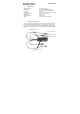
PowerBox Sensor 2. Specification Operating voltage: Power supply: 4.0 Volts to 9.0 Volts 2 x 5-cell NiCd or NiMH batteries, or 2 x 2-cell Lithium-Polymer batteries 5.0 Amps approx. 0.35 Volts (diode / regulator losses) 2 x 5.9 Volts (+/- 0.1 Volt) approx. 5µA -10°C to +75°C 35 g (complete incl. all cables) Max. load: Voltage loss: Voltage stabilisation: Idle current: Temperature range: Weight: 3. Connections and controls Connect the two batteries using the two UNI connectors.
PowerBox Sensor 4. Operating and Safety Notes Be sure to use top-quality batteries of low internal resistance to power your receiving system. Do not use receiver batteries of low capacity, as one pack may be required to provide full power to the system for the whole of a flight if the other battery should fail. Always use battery cells of the same type. We recommend that you use batteries with a capacity of at least 1700 mAh; for larger models we suggest packs of up to 3000 mAh capacity.
PowerBox Sensor 5. Using the Sensor-Switch The sensor buttons do not switch the current for the receiver and servos. The actual switching process is carried out by the two electronic switches in the POWER BOX Sensor, which are independent of each other. The controls on the front panel consist of three push-buttons, two green LEDs and one red LED. You will find two countersunk holes into which the mounting screws (supplied) fit. These are used to attach the switch to the model.
PowerBox Sensor 6. Guarantee conditions: During the production process each PowerBox Sensor undergoes a series of tests. We take the maintenance of the highest quality standards very seriously. We grant a 24 month guarantee on our products, valid from the initial date of purchase. The guarantee covers proven material faults, which will be corrected by us at no charge to you. We wish to emphasise expressly that we reserve the right to replace the unit if a repair is impossible for economic reasons.
PowerBox Sensor PowerBox Systems Modellbau-Deutsch Hindenburgstraße 33 86609 Donauwörth Tel: +49-0906-22559 Fax: +49-0906-22459 info@PowerBox-Systems.com www.PowerBox-Systems.