
User Manual

PowerBox Sensor
- 3 -
This ground-breaking overall design enables you to use the latest lightweight Lith-
ium-Polymer cells as well as standard 5-cell NC and Hydride batteries, without
exceeding the maximum voltage of 6.0 Volts.
As you would expect, we can also supply these modern Lithium-Polymer batter-
ies for your power supplies. We are the only manufacturer to rely exclusively upon
the Li-Po cells made by IONITY AG in Germany; we do not use any cell types
made in Asia.
The POWERBOX Sensor is equipped with LED power-on indicators for both power
circuits. If you switch one battery on, the associated green LED glows. When both
batteries are active, both LEDs light up.
The total voltage loss in the PowerBox Sensor (de-coupling diodes and voltage
regulators) is about 0.35 V, which is so low that the volume of waste heat is almost
negligible. The specified maximum continuous current is 5.0 Amps, which means
that it easily cope with 6 - 8 sta nd a rd se rvo s or 5 - 7 digital servos.
However, the rated continuous current of 5.0 A does not reflect the capacity of the
electronics; it is a function of the size of heat-sink employed. The electronic circuit is
able to handle twice the specified power without problem.
The heat-sink is mounted on the rear of the unit, and it is important to ensure that
the waste heat generated can be dissipated efficiently through this component. If
you notice that the heat-sink becomes hot in use (above 60° Celsius), this is a reli-
able indication that the servos you are using are consuming a disproportionate
amount of energy (power). Check your servos, linkages, pushrods etc. !
The unit features double battery and receiver cables, each with 0.34 mm² conduc-
tors. This means that voltage drop in the cables is very slight even at maximum
load.
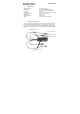
The schematic circuit diagram below
is intended to clarify the inter-related
functions of the POW ER BOX Sen-
so r . It shows in graphic form how the
indi vidual components are linked to-
gether.