
User Manual

PowerBox Sensor
- 6 -
5. Using the Sensor-Switch
The sensor buttons do not switch the current for the recei ver and servos. The ac-
tual switching process is carried out by the two electronic switches in the POWER
BOX Sensor, which are independent of each other.
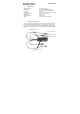
The controls on the front panel consist of three push-buttons, two green LEDs and
one red LED.
You will find two countersunk holes into which the mounting screws (supplied) fit.
These are used to attach the switch to the model.
The push-buttons are marked “SET” and “I” and “II”.
The purpose of the slightly recessed “SET” button is to prepare and execute a
switching process. Holding the “SET” button pressed in for about one second
“arms” both internal switches, and the red LED lights up. You can now switch either
or both power circuits on by pressing the other push-buttons “I” and “II”. This
method of switching allows you to check each power circuit or battery separately.
To switch off the POWER BOX Sen sor, first hold the “SET” button pressed in,
then press the push-buttons “I” and “II” in turn to switch both batteries off again.
This new switching system as our own in-house devel opment, and offers you the
highest possible standard of security.
When the electronic switches are in the “stand-by” state, i.e. the batteries are
switched off, they draw an idle current of about 5 micro-Amps. This corresponds to
a small fraction of the self-discharge rate of normal batteries.
However, if you do not intend to use your model for a long period we recommend
that you disconnect them from the POWER BOX Sensor, especially if you are us-
ing a Lithium-Polymer battery.
The POWER BOX S ensor is virtually impervious to vibration, but it is still good
practice to mount the unit in an area of the model where vibration levels are low.
Please note that the GRP fuselage sides of a power model are not suitable, as they
are always subject to considerable vibration. You can remedy the situation by cut-
ting a ply plate (2 - 3 mm thick) about 3 cm larger than the switch aperture, and
gluing it in the appropriate position. The plate damps the vibration, and at the same
time provi des plenty of “meat” into which the retaining screws of the POWER BOX
Sensor can “bite”.