
User Manual


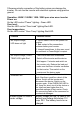

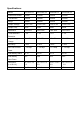


Cables: Make sure to use the correct cables. A chart is provided below,
for your reference:
Max. Watt Output DC Amps Req’d
Wire Gauge
150W 15A #14
300W 30A #10
600W 60A #6 or 2 x #10
1000W 100A
#2 or 2 x #6
1500W 150A
#2 or 2 x #6
2200W 220A
#2 or 2 x #6
Connection to the battery
-Lay the flexible connecting cable (positive) and (negative) from the
battery to the connecting terminals of the inverter (take cable cross
section from the table).
-Connect first the positive, then the negative cable.
! Make sure the terminals are not reversed!
Reverse polarity connection will blow the internal fuses. This will void the
warranty.
-Lay the flexible chassis ground cable from the chassis of the vehicle to
the chassis ground on the rack of the inverter.
-Connect the chassis ground.