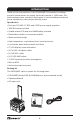
Model/Modelo PG1800WP Operating Manual Mobile Power Center English page 1 Version 1 Copyright ©2013 Sumec North America QUESTIONS? Our Customer Service staff is ready to provide assistance. In the case of a damaged or missing part, most replacement parts ship from our facility. For immediate help with assembly, or for additional product information, email support@sumec-na.com SAVE THIS MANUAL FOR REFERENCE You will need this manual for safety instructions, operating procedures, and Warranty.
Sumec North America 3939 Royal Dr. NW, Suite 234 Kennesaw, GA, 30144 USA Telephone: 1-866-902-9690 E-mail: support@sumec-na.
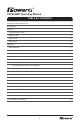
PG1800WP Operating Manual TABLE OF CONTENTS Important Safety Instructions 2 Introduction 4 Feature 9 System Control Panel 9 Output Panel 12 Input Panel 12 Back Panel 13 Operation 15 Working Mode 15 Output-Only Mode 15 Charging-Only Mode 15 Simultaneous Charging and Output Mode 16 Recharging 17 Charging Options 17 Charging with the Built-in AC Charger 17 Charging with Solar Panels 17 Expand the Solar Panels 17 Battery Self-discharge and Shelf Life 18 Troubleshooting 19 S
IMPORTANT SAFETY INSTRUCTIONS Misuse of the PG1800WP may result in injury to the user and/or damage to property. Read, understand and follow all CAUTION and WARNING statements contained in this manual. CAUTION statements identify conditions or practices that may result in damage to the PG1800WP or to other equipment. WARNING statements identify conditions that may result in personal injury or loss of life. This chapter contains important safety and operating instructions.
IMPORTANT SAFETY INSTRUCTIONS WARNING: Heat Hazard The PG1800WP’s internal inverter components may become uncomfortably warm, reaching 140°F (60°C) during prolonged operation. Ensure at least 6” (15 cm) of air space is maintained on all sides and on top of PG1800WP. During operation, keep away from materials that could be ignited by high temperatures such as blankets, pillows and sleeping bags, etc.
INTRODUCTION Thank you for your purchase of the PG1800WP. This system is a batterypowered system which can supply electrical power up to 1440 watts. This mobile energy center operates a wide variety of roles including recreational power, emergency power and productivity power.
INTRODUCTION Why need to “store” or “generate” power? In today’s modern society, more and more of our daily lives depend upon the electricity supplied by our local utilities. Most of this power is derived from fossil fuel sources i.e. coal, petroleum or natural gas. Many countries and communities have recognized the need to diversify where our energy comes from and have begun to transition to other forms of power generation.
INTRODUCTION vices to be charged with 12 VDC car type sockets, i.e. car charger). • Self-contained wheeled chassis (allows the entire unit to be moved freely like a portable gas generator). How can Mobile Power Center help me in an average short term power outage? In the event of a power outage, most people are limited to handheld flashlights, cell-phones and candles. That’s about the extent of your emergency kit. If the power is off for more than 1 hour people start to feel an impact to their lives.
INTRODUCTION is managing the loads. You can easily do this by monitoring the display panel which tells you the battery capacity left and current wattage draw from the unit (how much power you are using). The lower the draw, the longer the run time. If the power stayed off into the night, you could wheel the unit into your bedroom, plug in the all important alarm clock and cell phone and sleep worry free. No fumes no noise.
INTRODUCTION Option 2 Use the Mobile Power Center and a small gasoline generator as a team effort. Run your generator and 12 VDC solar panel to charge the Mobile Power Center during the day. Use the Mobile Power Center alone at night to cut noise and fuel usage. Option 3 Do the 3 way system. Mobile Power Center + 240 watts of panels + gasoline generator. Use the Mobile Power Center and panels as a primary and only use the generator on cloudy or low sunlight days to recharge the unit.
FEATURE 1. System Control Panel Press ON/OFF button for 0.5 second: Self-test mode (Note: Real color of display is blue) Figure 1 Control Panel Power On To power-on the PG1800WP, press and hold the ON/OFF button for approximately one-half second and release the button when the unit beeps. The PG1800WP will then be activated and the LCD panel will display the self-test’s progress. All indicators will be illuminated at the same time.
FEATURE LCD Display Backlight The PG1800WP’s LCD display backlight comes pre-programmed from the factory to briefly light the panel and then turn off automatically. If you prefer, you can reprogram the backlight to stay on until turned off manually instead of turning off automatically. To switch the backlight to manual-mode, press and hold the ON/OFF button for approximately four seconds.
FEATURE NOTICE: If Error code “E05” is displayed, the battery should be recharged using the AC charger, solar charge controller, or any of the other available charging options. Solar charging indicator When the PG1800WP is connected to a solar panel, the solar charging indicator will be illuminated. When the solar panel is initially connected (or disconnected), the LCD display’s backlight will be illuminated for approximately five seconds and the unit will beep.
FEATURE 2. Output Panel 120 VAC Output Outlets 5 VDC USB Outlets USB Output DC Output USB Output DC Output AC Output AC Output 12 VDC Outlets Figure 5 Output panel The Output Panel contains a total of six electrical outlets: • Two 5 VDC USB outlets provide power whether or not the PG1800WP is powered on. • Two 120 VAC outlets provide 120 V / 60 Hz power only when the PG1800WP is powered on. • Two 12 VDC car lighter outlets provide power whether or not the PG1800WP is powered on.
FEATURE 3.2 GFCI: 20 A Built-in GFCI for 120 VAC output. 3.3 Fuse set: 3.3.1 3.3.2 3.3.3 Figure 7 Fuse set 3.3.1 Solar input fuse: one 20 A / 32 VDC. 3.3.2 DC car lighter output fuses: two 15 A / 32 VDC. 3.3.3 Jump start fuses: seven 30 A / 32 VDC. 3.4 Vent: the vent for inner fan. WARNING: Always maintain at least 6” (15 cm) of empty air space around all sides of the PG1800WP’s cabinet to allow for proper cooling whenever the unit is operating. 4. Back Panel 4.5 4. 1 4. 2 4. 3 4.
FEATURE 4.3/4.3 Solar charging input: Charge the PG1800WP’s battery by connecting the red positive (+) and black negative (-) terminals to the solar panel. 4.5 Telescopic handle Telescopic handle release button: Use your thumb to press the release button, then pull and extend the telescoping handle.
OPERATION 1. Working mode Output-Only Mode – When the PG1800WP is in output-only mode, no input power is connected, but loads/devices are connected to the system. To enter the output-only mode, power on the PG1800WP by pressing and holding the ON/OFF power button for approximately one-half second and release the button when the unit beeps.
OPERATION While in charging-only mode, following indicators will be displayed: - Battery capacity 100% - Input power 100 w - Battery level Depending on the energy input’s source, the related charging indicators will also be illuminated: - Solar charging indicator - AC charging indicator Simultaneous Charging and Output Mode - One or more loads/devices are connected to outlets and one or more sources of input power are connected.
OPERATION 2. Recharging Mobile Power Center 2.1 Charging Options There are two charging options are possible with the PG1800WP: • Charging with the built-in AC Charger. • Charging with solar panels. Charging with the Built-in AC Charger To use the built-in AC charger, follow these steps: 1) Insert the AC charging cable into AC charging interface. 2) Plug the AC charging cable into a standard 120 VAC receptacle.
OPERATION 12V, I 1,P 1 12V, I 2,P 2 12V, I n, P n ...... 12V, 12V, I=I1+I 2+.......+ I n<20A or P=P1+ P2+....... Pn <240W Figure 13 Parallel connected solar panels NOTICE: Solar input exceeding 20 A will trip the PG1800WP’s solar charging fuse. CAUTION: Risk of damage to battery pack Polycrystalline or Monocrystalline modules for in 12 VDC system may be used for charging the PG1800WP. Using higher voltage panels or amorphous modules can damage the battery pack. 2.
TROUBLESHOOTING This section will help you quickly identify the source of most problems that can occur with the PG1800WP. If you have a problem with the PG1800WP, please review this chapter before contacting customer support. If you are unable to solve a problem and need to contact customer support, record the details on the form “Your System’s Information” on page 30. Error codes The following error codes may be displayed on the LCD display if the described fault conditions occur.
TROUBLESHOOTING E03 AC Output Overload Shutdown & AC Output Short-circuit Shutdown Unit shuts down. Remove excess AC loads. Reset of unit is required. An AC load applied to the system in Inverter-mode is above opera- To reset the unit, turn it OFF tion limit. and back ON. Flashing backlight changes from pink to red. After the alarm continues for one minute, the backlight and alarm will turn off. Only the error code will be shown continuously. E04 System Over Unit shuts down. Remove excess AC loads.
TROUBLESHOOTING E07 System Over System is still operating, but Unit continues to run. Temperature the system’s internal tempera- If the warning is ignored, Warning ture is close to the shutdown unit will eventually go to the limit. E04 fault condition. Backlight turns pink color and flashes. E08 E09 E10 Car lighter port #1 fuse is tripped Car lighter port #2 fuse is tripped DC car lighter output current is Reduce the load to DC car more than 15 A. lighter outlet.
SPECIFICATION This chapter contains the electrical specifications of the PG1800WP. Inverter Parameter Inverter Input Voltage Range 10.7 - 15.5 VDC Rated Input Voltage 12.
SPECIFICATION Maximum Charging Power 80 W /±10 W AC Input Frequency 60 Hz /± 1 Hz Output Voltage Bulk 14.7 VDC /± 0.2 VDC Float 13.7 VDC /± 0.2 VDC Recharge 12.6 VDC /± 0.2 VDC Charging Process Three-Stage Charging Process: • Bulk Stage • Absorption Stage • Float Stage Exchange Efficiency > 75% Protection High temperature, input-limited protection Solar Charger Parameter Solar charger Solar Input Voltage Range 10 - 24.5 VDC Maximum Output Current 20 A Output Voltage Bulk 14.
REPLACEMENT & INSTALLATION OF THE BATTERY Use only batteries meeting the following criteria: a. Battery type: Sealed lead-acid, AGM. b. Nominal voltage: 12 VDC. c. Capacity: 60 Ah or 80 Ah or 90 Ah or 100 Ah. d. Battery should comply with UL1989 standard. e. When installing the battery, make sure the polarity connections are correct. NOTICE: Battery has to be recharged immediately once purchased. All rechargeable batteries gradually discharge when left standing.
REPLACEMENT & INSTALLATION OF THE BATTERY The replacement steps of the battery are as follows: 1) Remove the six screws and open the upper cover. Screws 2) Remove the fixed bar securing the battery. Fixed bar 6-4/5 in . 13 in . 8-2/5 in. 3) Remove the connection of the POSITIVE (RED) cable from the battery, wrap the lug of the cable with electrical tape.
REPLACEMENT & INSTALLATION OF THE BATTERY PG1800WP’s positive and negative batteries. 8) Unwrap POSITIVE (RED) lug, connect the cables to the POSITIVE (RED) terminal of the battery and tighten. 9) Unwrap NEGATIVE (BLACK) lug, connect the cables to the NEGATIVE (BLACK) terminal of the battery and tighten. USED BATTERY DISPOSAL Batteries contain materials that are hazardous to the immune system, such as mercury, which can lead to health damage.
BATTERY OPERATING TIME PG1800WP output 120 VAC can be used to drive electrical appliances such as lamps, computers, electric tools, etc. USB output 5 VDC can supply power to cellular phone and digital products such as MP3 players, tablets, etc. Car lighter plug output 12 VDC can supply power to electrical products using 12 VDC. Working time of load: using 100 Ah battery as example (these data are for reference only).
WARRANTY What does this warranty cover? This Limited Warranty is provided by Sumec North America and covers defects in workmanship and materials in your PG1800WP. This warranty period lasts for 12 months from the date of purchase by the original purchaser. You will be required to demonstrate proof of purchase to make warranty claims. This Limited Warranty is transferable to subsequent owners but only for the unexpired portion of the Warranty Period.
RETURN POLICY Return using your preferred shipping method. NOTICE: some products include free shipping, so if you return one of these products, the actual outbound shipping costs will be deducted from your return refund. Opened Merchandise: There is a 30-day return policy with a 25% restocking fee to cover testing, cleaning and repackaging expenses for products that have been opened. Opened returns must be in sellable condition with original materials and packaging.
YOUR SYSTEM’S INFORMATION As soon as you open your Mobile Power Center package, record the following information and be sure to keep your proof of purchase. Serial Number ___________________________ Model Number PG1800WP Purchased From ___________________ Purchase Date ___________________________ If you need to contact Customer Service, please record the following details before calling. This information will help our representatives give you better service.