PDST24/PDST32 GASOLINE SNOW THROWER Owner's Manual 1-888-807-6660 American SD Power Inc This manual provides information regarding the operation and maintenance of these products. We have made every effort to ensure the accuracy of the information in this manual. We reserve the right to change this product at any time without prior notice. Please keep this manual available to all users during the entire life of the snow thrower.
TABLE OF CONTENTS 1. Important Safe Operation Practices...............................................................3 2. Assembling Your Snow Thrower ...................................................................6 3. Know Your Snow Thrower ..........................................................................6 4. Operating Your Snow Thrower ......................................................................10 5. Making Adjustments .............................................................
SECTION 1: IMPORTANT SAFE OPERATION PRACTICES WARNING: Engine Exhaust, some of its constituents, and certain vehicle components contain or emit chemicals known to the State of California to cause cancer, birth defects or other reproductive harm. DANGER: This machine was built to be operated according to the rules for safe operation in this manual. As with any type of power equipment, carelessness or error on the part of the operator can result in serious injury.
Operation 18. Never put your hand in the discharge or collector openings. Always use the clean-out tool provided to unclog the discharge opening. Do not unclog chute assembly while engine is running. Shut off engine and remain behind handles until all moving parts have stopped before unclogging. 19. Use only attachments and accessories approved by the manufacturer (e.g. wheel weights, tire chains, cabs etc.). 20. If situations occur which are not covered in this manual, use care and good judgment.
YOUR RESPONSIBILITY Restrict the use of this power machine to persons who read, understand and follow the warnings and instructions in this manual and on the machine. Do not modify engine Notice regarding Emissions To avoid serious injury or death, do not modify engine in any way. Tampering with the governor setting can lead to a runaway engine and cause it to operate at unsafe speeds. Never tamper with factory setting of engine governor.
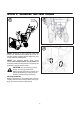
SECTION 2: ASSEMBLING YOUR SNOW THROWER 2 1 3 NOTE: References to right or left side of the snow thrower are determined from behind the unit in the operating position (standing directly behind the snow thrower, facing the handle panel). NOTE: This Operator’s Manual covers several models. Snow thrower features vary by model. Not all features referenced and pictured in this manual are applicable to all snow thrower models. CAUTION: Prior to operating your snow thrower, refer to Auger Control Test.
Attaching the Chute Assembly and Directional Control 1. Install the chute to the correct holes of outer shell's back. 2. Use the bolt and nut to fix the chute and bearing to the support base of chute. 3. After install the chute direction control,then make it drill through rotary shaft,let the chute direction control istall to the chute.Use nut to fix the chute direction control to the chute,and istall one gasket to the chute raised step. Install the plum-plastic-head bolt,locked equipment 4.
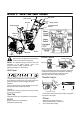
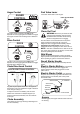
SECTION 3: KNOW YOUR SNOW THROWER Shift Lever Drive Control Gas Cap Auger Control Chute Assembly Chute Directional Control Clean-out Tool Oil Fill Skid Shoe Augers Choke Control WARNING: Read, understand, and follow all instructions and warnings on the machine and in this manual before operating. NOTE: For detailed starting instructions and more CHOKE LEVER Closed information on all engine controls, refer to the Engines manual packed separately and Starting The Engine on this manual.
Auger Control Fuel Valve Lever Fuel valve- Allows fuel to enter engine. AUGER CONTROL FUEL VALVE LEVER ON ON GO OFF Clean-Out Tool WARNING: Never use your hands to clear The auger control is located on the left handle. Squeeze the control grip against the handle to engage the augers and start snow throwing action. Release to stop. a clogged chute assembly. Shut off engine and remain behind handles until all moving parts have stopped before unclogging.
SECTION 4: OPERATING YOUR SNOW THROWER WARNING: If your home electrical Before Starting system is grounded, but a three-hole receptacle is not available, do not use your snow thrower’s electric starter. WARNING: Read, understand, and follow all instructions and warnings on the machine and in this manual before operating.
• To Engage Drive Pull the starter handle with a firm, rapid stroke. IMPORTANT: Do not release the handle and allow it to • snap back. Keep a firm hold on the starter handle and allow it to slowly recoil. • As the engine warms, slowly rotate the choke control to the OPEND position. If the engine falters, quickly rotate the choke control back to the CLOSEDposition and then slowly into the OPEND position again.
Chute Clean-Out Tool Tire Chains (on models so equipped) The chute clean-out tool is conveniently fastened to the rear of the auger housing with a mounting clip. Should snow and ice become lodged in the chute assembly during operation, proceed as follows to safely clean the chute assembly and chute opening: Tire chains should be used whenever extra traction is needed. If your unit is not equipped with tire chains, contact Customer Support as instructed for information regarding price and availability.
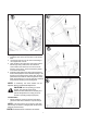
SECTION 5: MAKING ADJUSTMENTS WARNING: Never attempt to make any adjustments while the engine is running, except where specified in operator’s manual. 1 Shift Cable Adjustment If the full range of speeds (forward and reverse) cannot be achieved, refer to the figures to the right and adjust the shift rod as follows: 1. Rotate the shift arm clockwise as far as it will go. 2. Thread the ferrule up or down the shift rod until it aligns with the hole in the shift lever behind the handle panel.
Drive Control When the drive control is released and in the disengaged “up” position, the cable should have very little slack. It should NOT be tight. Check the adjustment of the drive control as follows: 1. With the drive control released, push the snow thrower gently forward. The unit should roll freely. 2. Engage the drive control and gently attempt to push the snow thrower forward. The wheels should not turn. The unit should not roll freely. 3.
SECTION 6: MAINTAINING AND SERVICING YOUR SNOW THROWER Auger Shaft WARNING: Before lubricating, repairing, or inspecting, disengage all controls and stop engine. Wait until all moving parts have come to a complete stop. • At least once a season, remove the shear pins on auger shaft. Spray lubricant inside shaft, around the spacers. Also lubricate the flange bearings found at either end of the shaft. See Figure 8.
Auger Belt Replacement To remove and replace your snow thrower’s auger belt, proceed as follows: 1. Remove the plastic belt cover on the front of the engine by removing the two self-tapping screws. • Drain the gasoline from the snow thrower, or place a piece of plastic under the gas cap. • Carefully pivot the snow thrower up and forward so that it rests on the auger housing. 2. Remove the frame cover from the underside of the snow thrower by removing four self-tapping screws which secure it. 3.
Drive Belt Replacement To remove and replace your snow thrower’s auger belt, proceed as follows: 1. Remove the plastic belt cover on the front of the engine by removing the two self-tapping screws. • Drain the gasoline from the snow thrower, or place a piece of plastic under the gas cap. • Carefully pivot the snow thrower up and forward so that it rests on the auger housing. 2. Remove the frame cover from the underside of the snow thrower by removing four self-tapping screws which secure it. 3. a.
Friction Wheel Removal 1 If the snow thrower fails to drive with the drive control engaged, and performing the drive control cable adjustment on page 14 fails to correct the problem, the friction wheel may need to be replaced. Follow the instructions below. Examine the friction wheel for signs of wear or cracking and replace if necessary • • Place the shift lever in third Forward (F3) position. Drain the gasoline from the snow thrower, or place a piece of plastic under the gas cap.
Augers • • IMPORTANT: NEVER replace the auger shear pins with anything other than OEM Part No.738-04124 replacement shear pins. Any damage to the auger gearbox or other components as a result of failing to do so will NOT be covered by your snow thrower’s warranty. The augers are secured to the spiral shaft with four shear pins and cotter pins. If the auger should strike a foreign object or ice jam, the snow thrower is designed so that the pins may shear. Refer to Figure 8.
SECTION 8: TROUBLE SHOOTING GUIDE Trouble Possible Cause(s) Corrective Action Engine fails to start Fuel tank empty, or stale fuel. Fill tank with clean, fresh gasoline. Fuel will not last over thirty days unless a fuel stabilizer is used. Clean fuel line. Turn the fuel valve lever to the On position. Clean, adjust gap or replace. Insert key into ignition switch. Connect spark plug wire.
SECTION 9: PARTS LIST 21
1 Washer,Bell,ij20×ij10.5×2 2 Shells PadM10 3. Hex Screw,3/8-16×27 l=44 S=14 4 Screw,Self-tapping5/16-18×19 S=12.5 5 Washer,Bell, 6 Crank Assembly,Chute 7 Nut,Flange Locking Hexagon5/16-18 S=12.5 8. Plastic ball 9. Handle,Lower,Snow 10 Nut,Plum Plastic 11 Bolt,Plum,Plastic 12 Hand,Upper,RH 13 Screw,Carriage,5/16-18×51 dk=18 14 Screw,Self-tapping,1/4-20×20 l=38 S=11 15 Screw,Shoulder,10#-24×34 Dyke=ij9 16 Nut,Hex Look,10#-24 S=9.
PARTS LIST 23
3. 4. 5. 6. 7. 8. 9. 10. Hex Screw,5/16-24×19 S=12.5 Washer,Bell,ij24×ij8×2 Wheel,Assembly Complete Spacer Friction Disc,Wheel Hex Screw,ij31×ij20×1.6 Friction Disc,Wheel Ring E-Type,GB/T896-1986 15 11 Bearing 6203 RSNRC 3 12 Screw,Self-Tapping,ST1/4-20×16- ij9.40×2.8-ij 13.7×2 S=9.5 13 Screw,self-tapping,1/4-20×26 S=9.5 14 Screw,self-tapping, ST1/4-20×16 S=9.5 15 Wheel,Rubber 16 Guide Bracket, Front, Auger Cable 17.
PARTS LIST(ST24) 25
1. Housing, Bearing 2. Bushing, Flange 3. Washer,Bell,ij38×ij19.2×0.8 4. Bushing, Flange 5. Spiral Assembly,LH 6. Spacer 7. Shear Pin 8. Pin ,B-style 9. Washer,Bell,ij38×ij8×4 10. Seal,Oil,Outside 11. Housing.Auger,LH Reduced 12. Seal,Oil 13. Hex Screw, 5/16-24×22 S=12.5 14. Bearing,Flange,Small 15. Washer,Flatij28×ij13×1.5 16. Shaft,Worm 17. Pin,Dowel 18. Collar,Thrust 19. Pulley Assembly 20. Bearing,Flange,Big 21. Nut,Hex Look,5/16-18 S=12.5 22. Washer,Bell,M8 23. Bearing,HK1010 24.
PARTS LIST(ST32) 27
1. Housing, Bearing 2. Bushing, Flange 3. Washer,Bell,ij38×ij19.2×0.8 4. Bushing, Flange 5. Spiral Assembly,LH 6. Spacer,Short 7. Shear Pin 8. Pin ,B-S tyle 9. Spacer,Long 10. Seal,Oil,Outside 11. Housing.Auger,LH Reduced 33. Nut,Hex Look,5/16-18 S=12.5 34. Shoe,Slide 35. Nut,Hex Look,3/8-16 S=14 36. Plate,Shave 37. Screw,Self-Tapping1/4-20×19 S=9.5 38. Impeller Assembly 39. Arm,Tension 40. Mount,Clean Out Tool 41. Clean Out Tool 42. Nut,Flange Lock, Plum 43. Bolt,Carriage,5/16-18×51 dk=18 44.