PowerLogic® COM128 RS-232 to RS-485 Converter Installation and Operation Guide August 2006
Conventions Throughout this operation manual, the following methods are used to highlight important information. NOTE Describes important considerations related to a device setup, feature or application. CAUTION Alerts you to a condition which could potentially cause damage to the device or other external equipment. WARNING or DANGER Warns you to avoid conditions that could potentially cause serious personal injury and/or equipment damage.
Table of Contents COM128 FEATURES ................................................................................................. 1 1 INTRODUCTION ........................................................................................................ 2 2 Physical Features ..................................................................................................... 3 2.1 RS-232 Panel .............................................................................................................
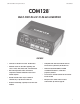
COM128 Installation and Operation Manual Schneider Electric COM128 TM MULTI-PORT RS-232 TO RS-485 CONVERTER FEATURES • Connects one RS-232 line to four RS-485 buses. • Automatic baud rate detection supporting data rates of 1200, 2400, 4800, 9600, and 19200 baud. • • • RTS/CTS handshaking capability for use with radio Works directly with M-SCADA, L-SCADA and PowerView software, or with other proprietary software.
COM128 Installation and Operation Manual 1 INTRODUCTION Schneider Electric DTE OR DCE OPERATION The COM128 is used to interface a single RS-232 communications line to up to four RS-485 communications buses. The COM128 is switch-selectable to act in DTE or DCE mode. An RS-232 port is provided for each mode, eliminating the need for null-modems. The RS-485 standard restricts each RS-485 bus to supporting 32 or fewer devices connected to it.
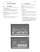
COM128 Installation and Operation Manual 2 Schneider Electric PHYSICAL FEATURES 2.2 RS-485 PANEL The RS-485 panel of the COM128 is illustrated in Figure 2.2.1. 2.1 RS-232 PANEL RS-485 PORTS The RS-232 panel of the COM128 is illustrated in Figure 2.1.1. DC SUPPLY CONNECTORS These connections allow the COM128 to be powered from a wide range of DC voltage sources, including the supplied adapter. See Chapter 4 for additional information. These four ports connect the COM128 to the four RS-485 buses.
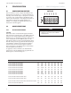
COM128 Installation and Operation Manual 3.2 MODE DESCRIPTIONS 3.2.1 RS-485 FLOW CONTROL ON 1 2 3 4 5 SW6 These six switches are used to configure the COM128 for the desired operation (see Figure 3.1.1). A switch is ON when it is in the UP position. The following is a description of each mode of operation. A list of switch settings for the different modes follows each mode description. The configuration switches are only read when control power is initally applied to the COM128.
Schneider Electric COM128 Installation and Operation Manual 3.2.2 SPEED COMPENSATION APPLICATION For use with DCE devices that require very accurate baud rate input. Typical uses are with high speed dial up modems. This mode can be programmed to either ignore the Carrier Detect (CD) input of its RS-232 DTE port or require that CD be asserted by the DCE device before data is transmitted by the COM128 to the DCE device.
Schneider Electric COM128 Installation and Operation Manual 3.2.4 RS-485 DATA BUFFERING WITH TRANSMISSION DELAY AFTER RTS ASSERTION monitor the RS-232 DTE port for data and continues to pass data to the RS-485 port until there is no data coming into the RS-232 port. APPLICATION RS-485 TO RS-232 DATA FLOW This mode is very similar to the RTS / CTS mode. The COM128 buffers data from the RS-485 ports, asserts its RTS output then transmits data out of the DTE port after a programmable time delay.
COM128 Installation and Operation Manual Schneider Electric 4 INSTALLATION 4.2.2 4.1 DC SUPPLY CONNECTIONS PORT SELECTION An IBM-compatible PC acts as a DTE (Data Terminal Equipment) RS-232 device. Therefore, the computer’s RS-232 port should be connected to the DCE port on the COM128. Refer to Figure 4.2.2. The COM128 is shipped with a 9 VDC adapter which plugs into the adapter receptacle. Use only the adapter provided with the COM128 for this particular powering application.
COM128 Installation and Operation Manual 4.2.3 Schneider Electric CONNECTION TO A MODEM PORT SELECTION A telephone or radio modem typically acts as a DCE RS-232 device. Therefore, the modem’s RS-232 port should be connected to the COM128’s DTE RS-232 port. Refer to Figure 4.2.3. SWITCH SETTINGS To properly communicate with the modem, the COM128 must be configured as a DTE RS-232 device .
COM128 Installation and Operation Manual 4.3 4.3.1 Schneider Electric RS-485 BUS CONNECTIONS 4.3.3 CONVERTOR CONNECTIONS Devices on an RS-485 bus are connected in a point-to-point configuration, with the (+) and (-) terminals of each device connected to the associated terminals on the next device. This is illustrated in Figure 4.3.3a. The RS-485 port of the COM128 provides screw down, captured wire type terminal blocks that unplug from the main chassis to simplify wiring.
DTE PORT DCE PORT PORT A PORT B PORT C PORT D Computer or Modem DTE PORT DCE PORT RS-232 PORT A PORT B PORT C PORT D RS-232 to RS-485 Converter COM128 RS-485 LOOP TOPOLOGY Computer or Modem COM128 RS-485 RS-232 to RS-485 Converter RS-232 RS-485 10 SHLD SHLD SHLD SHLD RS-485 STRAIGHT-LINE TOPOLOGY RS-485 PORT RS-485 Cable SHLD SHLD RS-485 PORT RS-485 Cable SHLD RS-485 PORT SHLD SHLD SHLD RS-485 PORT SHLD RS-485 PORT AWG 22 shielded twisted pair. Overall length: 4000 ft.
COM128 Installation and Operation Manual Schneider Electric CALCULATING OVERALL CABLE LENGTH When determining the overall length of an RS-485 communication straight-line or loop connection, it is important to account for all cable segments. For example, when RS-485 connections to the device are made via an intermediate terminal block (Figure 4.3.2), the lengths of cable between the device and the terminal block must be added to the total cable distance.
RS-485 Topologies to Avoid DTE PORT DCE PORT PORT A PORT B PORT C PORT D Computer or Modem DTE PORT DCE PORT RS-232 PORT A PORT B PORT C PORT D RS-232 to RS-485 Converter COM128 RS-485 T-CONNECTION Computer or Modem COM128 RS-485 RS-232 to RS-485 Converter RS-232 RS-485 12 3-way star connection point not allowed SHLD RS-485 STAR CONNECTION Figure 4.3.
COM128 Installation and Operation Manual 6 Schneider Electric TECHNICAL SPECIFICATIONS FEATURES ELECTRICAL RATINGS Isolation: 750 V between RS-232 and RS485 ports Power Supply: Standard: 9 VDC @ 500 mA (120 VAC adapter supplied) Baud Rates Supported: 1200, 2400, 4800, 9600, 19200 RS-232 Ports: One DTE (Male DB9) One DCE (Male DB9) RS-485 Ports: Four 3-pin, pluggable terminal blocks, each with (+), (-), and shield (SHLD) terminals Alternate: 2-pin pluggable terminal block accepts 9-30 VDC Power
COM128 Installation and Operation Manual 7 COM128 OPTIONS -UNI OPTION The -UNI option is a universal power supply that allows the COM128 to be powered from any standard international voltage and frequency. Schneider Electric -IND OPTION The -IND option is a universal power supply that allows the COM128 to be powered from any standard international voltage and frequency. The power supply is designed for industrial applications where it can be mounted on the wall or door of a cabinet. Refer to Figure 7.
COM128 Installation and Operation Manual Figure 7.
Figure 7.2.
PowerLogic COM 128 Installation and Operation Manual For further assistance please contact us at: Schneider Electric Power Monitoring and Control 2195 Keating Cross Road Saanichton, BC Canada V8M 2A5 Tel: 1-250-652-7100 295 Tech Park Drive, Suite 100 Lavergne, TN 37086 USA Tel: 1-615-287-3400 Electropole (38 EQI) 31, rue Pierre Mendès France F - 38050 Grenoble Cédex 9 Tel : + 33 (0) 4 76 57 60 60 Getting technical support: Contact your local Schneider Electric sales representative for assistance or go to