CX1400/3500/5500 Portable Generator Owner’s Manual 001593 MODEL:________________________ SERIAL:________________________ DATE PURCHASED:______________ WARNING This product is not intended to be used in a critical life support application. Failure to adhere to this warning could result in death or serious injury. (000209a) Register your Powermate product at: www.powermate.
Table of Contents Section 1 Introduction and Safety 1 Introduction ..................................... 1 Safety Rules .................................... 1 Safety Symbols and Meanings ........ 1 Exhaust and Location Hazards ....... 2 Electrical Hazards ........................... 3 Fire Hazards .................................... 3 Standards Index .............................. 3 Section 2 General Information and Setup .............................................. 4 Know Your Generator ................
Section 1 Introduction and Safety Introduction Thank you for purchasing a Powermate product. This unit has been designed to provide high-performance, efficient operation, and years of use when maintained properly. DANGER Indicates a hazardous situation which, if not avoided, will result in death or serious injury. (000001) WARNING Consult Manual. Read and understand manual completely before using product. Failure to completely understand manual and product could result in death or serious injury.
WARNING DANGER The exhaust system must be properly maintained. Do not alter or modify the exhaust system as to render it unsafe or make it noncompliant with local codes and/or standards. Failure to do so will result in death or serious injury. (000179a) Injury and equipment damage. Do not use generator as a step. Doing so could result in falling, damaged parts, unsafe equipment operation, and could result in death or serious injury. (000216) WARNING CAUTION DANGER Electrocution.
Electrical Hazards WARNING DANGER Electrocution. Contact with bare wires, terminals, and connections while generator is running will result in death or serious injury. (000144) Fire risk. Fuel and vapors are extremely flammable. Do not operate indoors. Doing so could result in death, serious injury, or property or equipment damage. (000281) WARNING DANGER Electrocution. Water contact with a power source, if not avoided, will result in death or serious injury. Explosion and fire risk.
Section 2 General Information and Setup 8 13 7 11 12 001593 10 9 Figure 2-1. Features and Controls TABLE 1.
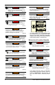
4 3 18 Replacement owner’s manuals are available at www.powermate.com. 5 Emissions 002341 1 19 6 2 Figure 2-4. CX5500 Control Panel (CSA/CARB) Know Your Generator The United States Environmental Protection Agency (US EPA) (and California Air Resources Board (CARB), for engines/equipment certified to California standards) requires that this engine/equipment complies with exhaust and evaporative emissions standards.
Connection Plugs 120 VAC, 30 Amp Receptacle 120 VAC, 20 Amp, Duplex Receptacle The 120 Volt outlet is overload protected by a 20 Amp push-to-reset circuit breaker. See Figure 2-5. Each receptacle will power 120 Volt AC, single phase, 60 Hz electrical loads requiring up to 2400 watts (2.4 kW) or 20 Amps of current. Use only high quality, wellinsulated, 3-wire grounded cord sets rated for 125 Volts at 20 Amps (or greater).
110/120 VAC, 30 Amp Receptacle Use a NEMA L5-30 plug with this receptacle (rotate to lock/unlock). Connect a suitable 3wire cord set to the plug and to desired load. The cord set should be rated for 125 Volts AC at 30 Amps (or greater). See Figure 2-9. Use this receptacle to operate 120 Volt AC, 60Hz, single phase loads requiring up to 3600 watts (3.6kW) of power at 30 Amps. The outlet is protected by a 30 Amp push-to-reset circuit breaker. 000844 Figure 2-9.
CX3500 See Figure 2-11. Install wheels as follows: 1. Slide axle pin (2) through wheel (1), M10 x 4mm flat washer (6), and frame. 2. Insert cotter pin (3) through axle (2). Bend tabs (of cotter pins) outward to lock into place. . Install frame foot assembly as follows: 1. Slide rubber foot (5), M6 nyloc nut (9), and foot spacer (4) onto M6 x 25 bolt (7). 2. Align through holes in frame rail and secure with M8 x 65 bolt (8). 2 1 6 4 8 5 9 3 7 002346 Figure 2-10.
. 10 2 12 3 7 12 13 5 1 6 8 9 11 4 001592 Figure 2-11. Wheel, Handle and Foot Assembly (CX5500) Add Engine Oil . CAUTION Engine damage. Verify proper type and quantity of engine oil prior to starting engine. Failure to do so could result in engine damage. (000135) SAE 30 10W-30 Synthetic 5W-30 1. Place generator on a level surface. 2. Verify oil fill area is clean. 3. Remove oil fill cap and wipe dipstick clean. See Figure 2-12. 000399 NOTE: Some units have more than one oil fill location.
Fuel DANGER Explosion and Fire. Fuel and vapors are extremely flammable and explosive. Add fuel in a well ventilated area. Keep fire and spark away. Failure to do so will result in death or serious injury. (000105) DANGER Do not overfill fuel tank. Fill to 1/2 in. of top of tank to allow for fuel expansion. Overfilling may cause fuel to spill onto engine causing fire or explosion, which will result in death or serious injury. (000166) Fuel requirements are as follows: • Clean, fresh, unleaded gasoline.
Section 3 Operation Operation and Use Questions Call Powermate customer service at 1-800445-1805 with questions or concerns about equipment operation and maintenance. Before Starting Engine 1. Verify engine oil level is correct. 2. Verify fuel level is correct. 3. Verify unit is secure on level ground, with proper clearance and is in a well ventilated area. Prepare Generator for Use DANGER Asphyxiation. Running engines produce carbon monoxide, a colorless, odorless, poisonous gas.
Know Generator Limits Edge Trimmer Overloading a generator can result in damage to the generator and connected electrical devices. Observe the following to prevent overload: • Add up the total wattage of all electrical devices to be connected at one time. This total should NOT be greater than the generator's wattage capacity. • The rated wattage of lights can be taken from light bulbs. The rated wattage of tools, appliances, and motors can be found on a data label or decal affixed to the device.
Starting Pull Start Engines WARNING Recoil Hazard. Recoil could retract unexpectedly. Kickback could result in death or serious injury. (000183) CAUTION Equipment and property damage. Disconnect electrical loads prior to starting or stopping unit. Failure to do so could result in equipment and property damage. (000136) 1. Unplug all electrical loads from the unit's receptacles before starting engine. 2. Place generator on a level surface. 3. See Figure 3-2. Open the fuel shut-off valve (A). 4.
Section 4 Maintenance and Troubleshooting Maintenance Preventive Maintenance Regular maintenance will improve performance and extend engine/equipment life. The manufacturer recommends that all maintenance work be performed by an Independent Authorized Service Dealer (IASD). Regular maintenance, replacement or repair of the emissions control devices and systems may be performed by any repair shop or person of the owner’s choosing.
Change Engine Oil . WARNING SAE 30 Accidental start-up. Disconnect spark plug wires when working on unit. Failure to do so could result in death or serious injury. (000141) 10W-30 Synthetic 5W-30 000399 Inspect Engine Oil Level WARNING Risk of burns. Allow engine to cool before draining oil or coolant. Failure to do so could result in death or serious injury. (000139) Inspect engine oil level prior to each use, or every 8 hours of operation. 1. Place generator on a level surface. 2.
Service Spark Plug To service spark plug: 1. Clean area around spark plug. 2. Remove and inspect spark plug. 3. Inspect electrode gap with wire feeler gauge and reset spark plug gap to 0.0280.031 in (0.7-0.8 mm). See Figure 4-4. 3. Remove screen (D) and replace if torn, perforated or otherwise damaged. If screen is not damaged, clean with commercial solvent. 4. Replace screen and retainer, secure with screw. 5. Install clamp. D A C B Figure 4-4.
• Cover unit with a suitable protective, moisture resistant cover. • Store unit in a clean and dry area. • Always store generator and fuel away from heat and ignition sources. Prepare Fuel System for Storage Fuel stored over 30 days can go bad and damage fuel system components. Keep fuel fresh, use fuel stabilizer. If fuel stabilizer is added to fuel system, prepare and run engine for long term storage. Run engine for 10-15 minutes to circulate stabilizer throughout fuel system.
Troubleshooting PROBLEM CAUSE CORRECTION Engine is running, but AC output is not available. 1. Circuit breaker OPEN. 2. Poor connection or defective cord set. 3. Connected device is bad. 4. Fault in generator. 5. GFCI receptacle is OPEN (if equipped). 1. Reset circuit breaker. 2. Check and repair. 3. Connect another device that is in good condition. 4. Contact IASD. 5. Correct ground fault and press reset button on GFCI receptacle (if equipped).
Notes Owner’s Manual for Portable Generator 19
20 Owner’s Manual for Portable Generator
Part No. 10000001749 Rev. B 05/17/16 ©2016 Powermate All rights reserved. Specifications are subject to change without notice. No reproduction allowed in any form without prior written consent from Powermate. Powermate, LLC S45 W29290 Hwy. 59 Waukesha, WI 53189 1-800-445-1805 www.powermate.