Operator Manual 200-2143 Manuel de l’opérateur Manual del operador Revision D Electric Two–Stage Air Compressors Compresseurs d’air électriques à deux étapes Compresores de aire eléctricos de dos etapas WARNING: Read and understand all safety precautions in this manual before operating. Failure to comply with instructions in this manual could result in personal injury, property damage, and/or voiding of your warranty.
TABLE OF CONTENTS SAFETY GUIDELINES . . . . . . . . . . . . . . . . . . . . . . . . . . .3 OVERVIEW . . . . . . . . . . . . . . . . . . . . . . . . . . . . . . . . . . .6 Basic Air Compressor Components . . . . . . . . . . . . .6 INSTALLATION . . . . . . . . . . . . . . . . . . . . . . . . . . . . . . . .8 Installing The Compressor . . . . . . . . . . . . . . . . . . . . .8 Typical Installation . . . . . . . . . . . . . . . . . . . . . . . . . .10 ELECTRICAL POWER REQUIREMENTS . . . . . . . . . . .
SAFETY GUIDELINES The following information relates to protecting YOUR SAFETY and PREVENTING EQUIPMENT PROBLEMS. To help you recognize this information, we use the following symbols. Please read the manual and pay attention to these sections. DANGER: – A POTENTIAL HAZARD THAT WILL CAUSE SERIOUS INJURY OR LOSS OF LIFE. WARNING: – A POTENTIAL HAZARD THAT COULD CAUSE SERIOUS INJURY OR LOSS OF LIFE. CAUTION: – A POTENTIAL HAZARD THAT MAY CAUSE MODERATE INJURY OR DAMAGE TO EQUIPMENT. WARNING 1. 2.
CONSIGNES DE SÉCURITÉ Les informations suivantes concernent VOTRE SÉCURITÉ et LA PROTECTION DU MATÉRIEL CONTRE LES PANNES. Pour vous aider à identifier la nature de ces informations, nous utilisons les symboles suivants. Veuillez lire le manuel et prêter attention à ces sections. DANGER: – DANGER POTENTIEL POUVANT ENTRAÎNER DE GRAVES BLESSURES OU LA MORT. AVERTISSEMENT: – DANGER POUVANT CAUSER DES BLESSURES GRAVES VOIRE MORTELLES.
PAUTAS DE SEGURIDAD La información que sigue se refiere a la protección de SU SEGURIDAD y la PREVENCIÓN DE PROBLEMAS DEL EQUIPO. Como ayuda para reconocer esta información, usamos los siguientes símbolos. Lea por favor el manual y preste atención a estas secciones. PELIGRO: - UN POSIBLE RIESGO QUE CAUSARÁ LESIONES GRAVES O LA PÉRDIDA DE LA VIDA. ADVERTENCIA: - UN RIESGO POTENCIAL QUE PODRÍA PROVOCAR GRAVES LESIONES O MUERTE.
OVERVIEW \ VUE D’ENSEMBLE \ RESUMEN GENERAL BASIC AIR COMPRESSOR COMPONENTS The basic components of the air compressor are the electric motor, pump, tank and pressure switch. The basic components of the air compressor are the electric motor, pump, pressure switch, and tank. The electric motor (see A) powers the pump. The electric motor is equipped with an overload protector and an automatic reset. If the motor becomes overheated, the overload protector will shut it down to prevent damage to the motor.
INSTALLATION / INSTALLATION vapeurs inflammables, celles–ci risques de prendre feu, causant ainsi un incendie ou une explosion. Utilisez toujours le compresseur dans une zone bien aérée. INSTALLING THE COMPRESSOR 1. 2. 3. Unpack the air compressor. Inspect the unit for damage. If the unit has been damaged in transit, contact Customer Service. Do this immediately, because there are time limitations to damage claims.
INSTALACION INSTALACION DEL COMPRESOR 1. 2. 3. Desembale el compresor de aire. Inspeccione la unidad por daños. Si la unidad ha sido dañada, comunîquese con el Centro de Servicio. Haga esto de inmediato, ya que el plazo permitido para presentar reclamaciones por daños está limitado.
COMPRESSOR CONTROLS / COMMANDES DU COMPRESSEUR / CONTROLES DEL COMPRESOR COMPRESSOR CONTROLS Main Power Disconnect Install a main power disconnect switch in the power line to the compressor, near the compressor’s location. It is operated manually, but when it is in the ON position, the compressor will start up or shut down automatically based on air demand. ALWAYS operate this switch to OFF when the compressor is not being used.
TYPICAL INSTALLATION / INSTALLATION TYPIQUE / INSTALACION TIPICA A B C D E F G H J K L M N P R T U V W 10 WARNING: Risk of bursting, resulting in injury. Never use Plastic pipe for compressed air. CAUTION: Never use lubricator for paint spraying or similar applications. ADVERTISSEMENT: Risque d’éclatement pouvant entraîner des blessures. N’utilisez jamais de tuyau en plastique pour de l’air comprimé.
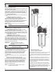
TYPICAL INSTALLATION / INSTALLATION TYPIQUE / INSTALACION TIPICA INSTALLATION Air dryers and after coolers An air dryer or aftercooler is installed directly in the air line. Moisture removal and air filtration As the air cools, moisture will condense in the lines. This moisture must be removed before it reaches the tool being used. To remove this moisture, run the main air line downhill to a moisture trap and drain. Air/water filters should also be installed in the positions shown.
ELECTRICAL POWER REQUIREMENTS SPÉCIFICATIONS DE L'ALIMENTATION ÉLECTRIQUE REQUERIMIENTOS DE ALIMENTACIÓN ELÉCTRICA ELECTRICAL WIRING Refer to the air compressor’s serial label for the unit’s voltage and amperage requirements. Ensure that all wiring is done by a licensed electrician, in accordance with the National Electrical Code. Use electrical conduit to protect the wiring.
BREAK-IN OF THE PUMP \ RODAGE DE LA POMPE \ MARCHA DE LA BOMBA BREAK-IN OF THE PUMP NOTE: The pump is shipped with break–in oil which should be changed after the first 8 hours of operation. To reduce maintenance and repair problems, use only a premium compressor oil. 1. Check the level of oil in the pump with the sight glass. The pump oil level must be between A and B. Do not overfill or underfill. 2. Make sure the power is connected at the power panel. 3. Open the petcock (see E).
OPERATING INSTRUCTIONS \ MODE D’EMPLOI \ INSTRUCCIONES OPERATIVAS DAILY STARTUP 1. 2. 3. Every day check the sight glass to ensure that the level of oil in the pump is at the required level. Close the tank petcock (see A). WARNING: High temperatures are generated by the pump. To prevent burns or other injuries, DO NOT touch the pump or transfer tube while the pump is running. Allow it to cool before handling or servicing. Keep children away from the compressor at all times.
OPERATING INSTRUCTIONS \ MODE D’EMPLOI \ INSTRUCCIONES OPERATIVAS SHUTDOWN 1. 2. Shut OFF the main power disconnect switch. Reduce pressure in the tank through the outlet hose. You can also pull the relief valve ring (see A) and keep it open to relieve pressure in the tank. CAUTION: Escaping air and moisture can propel debris that may cause eye injury. Wear safety goggles when opening petcock. 3. Open the petcock (see B) to allow moisture to drain from the tank. ARRÊT 1. 2.
PUMP LUBRICATION / LUBRIFICATION DE LA POMPE / LUBRICACION DE LA BOMBA OIL LEVEL Always operate the unit in a level position. Prior to start–up, check the sight glass to ensure that the oil in the pump is at the required level. The oil level should reach 1/8” above the red line on the sight glass. If the oil level is too low, remove the oil fill plug and add oil until the sight glass shows the correct level. Do not overfill or underfill; too much or too little oil will harm the pump.
PUMP LUBRICATION / LUBRIFICATION DE LA POMPE / LUBRICACION DE LA BOMBA CONDENSATION CAUTION: A rise in the oil level and a milky oil color indicate condensation is forming in the crankcase. This condensation must be drained immediately, or damage to the pump may occur. Condensation: Water condensing in the crankcase can occur under certain humid conditions or light duty cycling. This water must be removed from the pump to prevent damage.
PUMP LUBRICATION / LUBRIFICATION DE LA POMPE / LUBRICACION DE LA BOMBA CONDENSACIÓN PRECAUCION: El aumento del nivel del aceite y un color blanquecino indican que se está formando condensado en el cárter. Se debe purgar esta condensación inmediatamente, o podrá ocurrir daños en la bomba. Condensación: Bajo ciertas condiciones de humedad o de ciclos de trabajo liviano, se puede producir condensación de agua en el cárter. Se debe eliminar esta agua de la bomba para impedir daños.
MAINTENANCE \ ENTRETIEN \ MANTENIMIENTO MAINTENANCE WARNING: To avoid personal injury, always shut OFF the main power disconnect, and relieve all air pressure from the system before performing any service on the air compressor Regular maintenance will ensure trouble–free operation. Your electric powered air compressor represents high–quality engineering and construction; however, even high–quality machinery requires periodic maintenance.
MAINTENANCE \ ENTRETIEN \ MANTENIMIENTO BELT TENSION AND PULLEY ALIGNMENT WARNING: To avoid personal injury, always shut off and unplug the compressor and relieve all air pressure from the system before performing any service on the air compressor. NOTE: Drive belt tensioning and pulley alignment are done at the same time. They are discussed separately for clarity. ADJUSTING DRIVE BELT TENSION Proper belt tension and pulley alignment must be maintained for maximum drive efficiency and belt life.
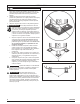
MAINTENANCE \ ENTRETIEN \ MANTENIMIENTO PULLEY ALIGNMENT To check pulley alignment, remove the belt guard and place a straightedge (see A) against the pump flywheel (see B). Measure and record the distance from the straightedge to the edge of the drive belt at point C. Then measure the distance from the straightedge to the edge of the drive belt again at points D and E. Both distances should be the same as at point C.
MAINTENANCE \ ENTRETIEN \ MANTENIMIENTO CLEANING THE AIR FILTER A dirty air filter will reduce the compressor’s performance and life. To avoid any internal contamination of the pump, the filter should be cleaned frequently, and replaced on a regular basis. Felt filters should be cleaned in warm, soapy water, rinsed, and allowed to air dry before reinstallation. Paper filters should be replaced when dirty. Do not allow the filter to become filled with dirt or paint.
SERVICE INTERVAL Perform the following maintenance at the intervals indicated below. Inspect and clean air filter . . . . . . . . . . . . . . . . . . . . . . . . . . . . . . . . . . . . . . . . . . . . .Weekly Check pump oil level . . . . . . . . . . . . . . . . . . . . . . . . . . . . . . . . . . . . . . . . . . . . . . . . . . .Daily Change pump oil . . . . . . . . . . . . . . . . . . . . . . . . . . . . . . . . . . . . .see PUMP LUBRICATION Operate the pressure relief valves . . . . . . . . . . . . . . .
TROUBLESHOOTING CHART Note: Troubleshooting problems may have similar causes and solutions. PROBLEM POSSIBLE CAUSE SOLUTION Excessive current draw trips circuit breaker of motor reset switch Low voltage/motor overload Check that power supply is adequate and that compressor is on a dedicated circuit Compressor stalls Low voltage to motor Furnish adequate power. Siezed pump Contact authorized service center. Air leaks Tighten or replace leaking fittings or connections. Do not overtighten.
TROUBLESHOOTING THE MAGNETIC STARTER PROBLEM POSSIBLE CAUSE SOLUTION COMPRESSOR WON’T RUN Motor hums but won’t turn Motor doesn’t hum Magnetic starter coil clicks Fuse blown in main panel if 3-phase system Check and replace fuse in main panel. Low voltage to motor Motor wired for wrong voltage.* Compressor starting under pressure Power leads to motor disconnected Check head unloader valve system. Motor burned out Replace motor. Check wiring and reconnect as needed.
DÉPANNAGE Remarque : Les problémes de dépannage peuvent avoir des causes et des solutions similaires. PROBLÈME CAUSE POSSIBLE SOLUTION Le prélèvement excessif de courant cause le déclenchement du disjoncteur ou de l’interrupteur de remise en marche du moteur Tension insuffisante/surcharge du moteur Vérifiez que l’alimentation est adéquate et que le compresseur est branché sur un circuit séparé. Vérifiez que le compresseur est branché sur son propre circuit.
DÉPANNAGE DU DÉMARREUR MAGNÉTIQUE PROBLÈME CAUSE POSSIBLE SOLUTION LE COMPRESSEUR NE FONCTIONNE PAS Le moteur ronfle, mais ne tourne pas Un fusible a sauté sur le tableau électrique principal si le système est triphasé Vérifier et remplacer le fusible sur le tableau électrique principal. Tension d’alimentation du compresseur trop basse Moteur câblé pour une tension incorrecte.* Démarrage du compresseur sous pression Vérifier le système à régulateur de pression de la tête.
CUADRO DE DETECCION DE FALLOS Nota: Los problemas de deteccion de fallos pueden tener causas y soluciones similares. PROBLEMA CAUSA POSIBLE SOLUCION Una extracción excesiva de la corriente hace saltar el cortacircuito o el interruptor de reposición del motor Voltaje bajo/sobrecarga del motor Verifique que el suministro de energía sea el adecuado y que el compresor se encuentre en un circuito exclusivo. Se detiene el compresor Bajo voltaje al motor Suministre la energía adecuada.
DETECCION DE FALLOS PARA EL ARRANCADOR MAGNETICO PROBLEMA CAUSA POSIBLE SOLUCION EL COMPRESOR NO FUNCIONA El motor realiza un zumbido pero no gira Se ha quemado un fusible en el panel principal si es un sistema trifásico Verifique y reemplace el fusible en el panel principal. Bajo voltaje al compresor El motor está conectado para un voltaje equivocado.* El compresor está arrancando bajo presión Verifique el sistema de válvulas de descarga de la cabeza.
PARTS AND SERVICE Replacement parts and service are available from your nearest authorized Service Center. If the need arises, contact Product Service as listed at right. When needing service, please contact the nearest authorized Service Center or call: When consulting with a Service Center or Product Service, refer to the model number and serial number located on the serial label of the compressor. Proof of purchase is required for all transactions and a copy of your sales receipt may be requested.