
Warranty


15
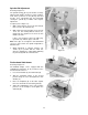
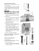
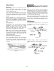
Spindle Assembly Installation
Refer to Figure 15. The fence guard (A) has been
removed for clarity.
The spindle assembly (B) is mounted to the arbor
(C) and secured with a draw bar (J) and nut (E).
Use the following procedure to install the spindle
assembly. Reverse the order to remove the
spindle.
When changing tools, making
adjustments, or doing clean-up and maint-
enance, always turn the machine off and unplug
the machine from its power source.
1. Raise the arbor (C) all the way using the
handwheel located on the front of the cabinet.
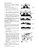
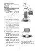
Locking the Arbor
2. Locate the spindle lock (F) accessible through
the door on the right side of the cabinet. Pull
out and rotate 90º right or left, resetting the
knob into the indent.
Turn the arbor (C) by hand until it locks, then
verify that it will not rotate.
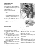
Installing the Spindle Assembly
3. Thread the nut (E) onto the threaded end of the
spindle (D) in the direction indicated by arrows
(A
1
, A
2
). Tighten securely by hand.
4. Thread the spindle assembly (B) and nut (E)
onto the arbor (C) and hand tighten only.
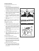
5. Insert the draw bar (J) through the opening in
the shaft (H) just below the drive belt (G). Turn
clockwise, fastening and securing it to the
spindle. Tighten the draw bar (J) with the
provided wrench (K).
6. Tighten the nut (E) with the wrench (K).
Shaper Cutter installation is described in the
following section. Note that at this time the
spindle holder is still locked.
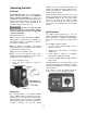
Spindle Assembly Removal
Referring to Figure 15:
The spindle holder must be locked as described in
Spindle Assembly Installation, step 2.
1. Remove the draw bar (J).
2. Loosen the nut (E) then, using the wrench (K)
continue to turn until the spindle attachment
breaks free of the arbor.
Figure 15