This .pdf document is bookmarked Operating Instructions and Parts Manual Single End Dovetailer Model DT45 Powermatic 427 New Sanford Road LaVergne, Tennessee 37086 Ph.: 800-274-6848 www.powermatic.com Part No.
Warranty and Service Powermatic warrants every product it sells against manufacturers’ defects. If one of our tools needs service or repair, please contact Technical Service by calling 1-800-274-6846, 8AM to 5PM CST, Monday through Friday. Warranty Period The general warranty lasts for the time period specified in the literature included with your product or on the official Powermatic branded website. • Powermatic products carry a limited warranty which varies in duration based upon the product.
Table of Contents Warranty and Service .............................................................................................................................. 2 Table of Contents .................................................................................................................................... 3 Warning................................................................................................................................................... 4 Introduction .....................
Warning 1. Read and understand the entire owner’s manual before attempting assembly or operation. 2. Read and understand the warnings posted on the machine and in this manual. Failure to comply with all of these warnings may cause serious injury. 3. Replace the warning labels if they become obscured or removed. 4. This dovetailer is designed and intended for use by properly trained and experienced personnel only.
21. Give your work undivided attention. Looking around, carrying on a conversation and “horse-play” are careless acts that can result in serious injury. 22. Maintain a balanced stance at all times so that you do not fall or lean against the cutter or other moving parts. Do not overreach or use excessive force to perform any machine operation. 23. Use the right tool at the correct speed and feed rate. Do not force a tool or attachment to do a job for which it was not designed.
Introduction This manual is provided by Powermatic covering the safe operation and maintenance procedures for a Model DT45 Single End Dovetailer. This manual contains instructions on installation, safety precautions, general operating procedures, maintenance instructions and parts breakdown. This machine has been designed and constructed to provide years of trouble free operation if used in accordance to instructions set forth in this manual.
Features of the DT45 Dovetailer Terminology Below are the terms used in this manual to identify types of cuts and measurements.
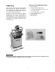
Contents of the Shipping Container Unpacking 1 2 1 Open shipping container and check for shipping damage. Report any damage immediately to your distributor and shipping agent. Do not discard any shipping material until the dovetailer is assembled and running properly. 1 2 1 1 Remove the box from inside the cabinet. Compare the contents of your container with the following parts list to make sure all parts are intact. Missing parts, if any, should be reported to your distributor.
Installation & Assembly Tools required for assembly forklift or hoist with straps/slings 11mm wrench (provided) [NOTE: A socket set with ratchet wrench may speed assembly] 4 and 5mm hex wrenches (provided) knife or wire cutter 1. 2. 3. 4. Remove the four screws and flat washers holding the machine to the pallet with an 11mm wrench, as shown in Figure 1. Place lifting straps through the two eyebolts at the top of the machine (Figure 2).
3. Tighten the four socket head cap screws. Installing Switch 1. Remove any protective wrapping from the switch. 2. Remove the two socket head cap screws from their holes on the left side of the frame with a 5mm hex wrench. See Figure 4. 3. Place the flange of the switch box over the holes, and re-insert the two socket head cap screws, as shown in Figure 4. 4. Tighten both socket head cap screws. Figure 4 Installing Dust Hood 1.
Grounding Instructions Electrical connections must be made by a qualified electrician in compliance with all relevant codes. This machine must be properly grounded to help prevent electrical shock and possible fatal injury. This machine must be grounded. In the event of a malfunction or breakdown, grounding provides a path of least resistance for electric current to reduce the risk of electric shock.
The temporary adapter should only be used until a properly grounded outlet can be installed by a qualified electrician. This adapter is not applicable in Canada. The green colored rigid ear, lug, or tab, extending from the adapter, must be connected to a permanent ground such as a properly grounded outlet box, as shown in Figure 9. 230 Volt Operation If 230 volt, single-phase operation is desired, the following instructions must be followed to convert from 115 to 230: 1.
Adjustments Disconnect machine from power source before making adjustments. Failure to comply may cause serious injury. Lower Work Support Inside the cabinet is a lower work support (Figure 13) which is used to support work pieces in the vertical position. To move this support up or down, loosen the locking handle (A, Figure 13). Tighten locking handle when finished.
Template Bar The four-sided template bar, shown in Figure 16, will allow you to create “half-blind” dovetails, where the dovetails are visible on only one side of the joint. It will create dovetails in one of four different “pitches” or centerlines. The available pitches are 1”, 1-1/2”, 2” and 2-1/2”. To change the pitch of a dovetail cut, proceed as follows: 1. 2. 3. 4. 5.
3. Continue to check the spacing by sliding the headstock across, until the dovetail cuts will be distributed evenly across the width of the workpiece. NOTE: This is an approximate method of determining by eye where to place the workpiece. A scale in inches and millimeters is mounted to the table if you need more precise measurements for the location of the dovetail cuts. 4. As noted, the position of the horizontal fence will affect the position of the vertical fence.
Buffer Pads The polyethylene buffer pads (shown in Figure 20) have slots through which they are secured to the fences by screws. These buffer pads at times may need to be re-positioned; for example, if a clamping bar is adjusted for a different thickness of workpiece, the buffer pad may need to be adjusted out of the way to prevent obstructing the clamping bar. To adjust a buffer pad, loosen the two hex cap screws (Figure 20) with a 13mm wrench. Slide the buffer pad as necessary.
Thickness of Tenon Cut To adjust the thickness of the tenon (male) cuts, you will change the depth of the tracer pin (Figure 22). 1. Disconnect machine from power source. 2. Loosen the locking handle on top the tracer pin (Figure 22) by turning it counter clockwise. 3. Insert a 5.5mm hex wrench into the end of the adjustment screw (Figure 22) and turn the adjustment screw as needed. To decrease the thickness of the tenon cut, turn the adjustment screw counterclockwise.
Drive Belt Tension The tightness of the belt that drives the spindle has been adjusted at the factory. Further adjustment may be necessary after the machine receives some use, as the belt may stretch slightly during the “breaking in” process. Belt tension can be adjusted by a socket head cap screw at the rear of the headstock (Figure 24) which slides the motor toward or away from the spindle. To tighten the belt, rotate this cap screw clockwise with a 6mm hex wrench.
IMPORTANT: Make sure the workpiece has been cut square before making dovetails. An out-of-square workpiece will result in poor dovetail joints. 1. Set the appropriate template size, fence positions, clamping bar thickness, and cutter depth for your particular job. Refer to “Adjustments” section starting on page 13. 2. Move the headstock all the way to the right and out of the way. 3. Place the drawer BACK on top the table and flush against the fence, with the bottom groove facing up and toward the fence.
10. Insert the LEFT SIDE piece and clamp it in vertical position on the lower work support and against the fence. (NOTE: The bottom grooves on both pieces will be face up, but will now be opposite the fences.) Again, make sure the edges are flush with the LEFT SIDE overlapping the edge of the BACK. 11. Continue the dovetailing procedure with the FRONT piece, making cuts “C” and “D” (Figure 25) until all four joints of the drawer have been cut.
3. Plywood has a tendency to chip out on exposed edges. A back-up board should be used as needed (see Figure 29). Maintenance Before doing maintenance on the machine, disconnect it from the electrical supply. Failure to comply may cause serious injury. If the power cord is worn, cut, or damaged in any way, have it replaced immediately. The table and other exposed metal parts should be kept clean and free of rust. A coat of paste wax will help protect the table from tarnishing.
Troubleshooting the DT45 Trouble Probable Cause Remedy Machine will not start/restart or repeatedly trips circuit breakers or blows fuses. Machine not plugged in. Verify machine is connected to power. Fuse blown, or circuit breaker tripped. Replace fuse, or reset circuit breaker. Cord damaged. Replace cord. Overload automatic reset has not reset. If the Dovetailer overloads on the circuit breaker built in to the motor starter, it takes time for the machine to cool down before restart.
Trouble Probable Cause Remedy On/off switch failure. If the on/off switch is suspect, you have two options: Have a qualified electrician test the switch for function, or purchase a new on/off switch and establish if that was the problem on changeout. Cutter in wrong position. Turn cutter towards the (+) or (-) mark [page 17]. Cutter dull or damaged. Sharpen or replace cutter. Dovetailed parts fit too tightly. Cutter not adjusted properly. Loosen set screws and turn cutter toward the (+) mark.
Parts List: Base Assembly Index No. Part No. Description Size Qty 1............... DT45-101.................Worktable .............................................................................................. 1 2............... DT45-102.................Base Guide Rod .................................................................................... 2 3............... TS-1523041 .............Socket Set Screw ...............................................M6x12 ...................... 15 4...........
Base Assembly 25
Parts List: Headstock Assembly Index No. Part No. Description Size Qty 1............... DT45-201.................Spindle Assembly (Index #2 thru #10).................................................... 1 2............... DT45-202.................Spindle Bearing Housing ....................................................................... 1 3............... DT45-203.................Ball Bearing (special)..........................................6005 B.P63 ................ 2 4............... DT45-204...
Headstock Assembly 27
Parts List: Cabinet Assembly Index No. Part No. Description Size Qty 1............... DT45-301.................Cabinet.................................................................................................. 1 2............... DT45-302.................Door ...................................................................................................... 1 3............... DT45-303.................Door Latch.....................................................................................
Electrical Connections – 115 volt 29
Electrical Connections – 230 volt 30
427 New Sanford Road LaVergne, Tennessee 37086 Phone: 800-274-6848 www.powermatic.