This .pdf document is bookmarked Operating Instructions and Parts Manual 12-inch Jointer Model 1285 For machines with serial no. 13102013913 and higher Powermatic 427 New Sanford Road LaVergne, Tennessee 37086 Ph.: 800-274-6848 www.powermatic.com Part No.
1.0 Warranty and Service Powermatic warrants every product it sells against manufacturers’ defects. If one of our tools needs service or repair, please contact Technical Service by calling 1-800-274-6846, 8AM to 5PM CST, Monday through Friday. Warranty Period The general warranty lasts for the time period specified in the literature included with your product or on the official Powermatic branded website. • Powermatic products carry a limited warranty which varies in duration based upon the product.
2.0 Table of Contents Section Page 1.0 Warranty and Service ..................................................................................................................................... 2 2.0 Table of Contents ........................................................................................................................................... 3 3.0 Warnings .........................................................................................................................................
3.0 Warnings 1. Read and understand the entire owner’s manual before attempting assembly or operation. 2. Read and understand the warnings posted on the machine and in this manual. Failure to comply with all of these warnings may cause serious injury. 3. Replace the warning labels if they become obscured or removed. 4. This jointer is designed and intended for use by properly trained and experienced personnel only.
19. Keep visitors a safe distance from the work area. Keep children away. 20. Make your workshop child proof with padlocks, master switches or by removing starter keys. 21. Give your work undivided attention. Looking around, carrying on a conversation and “horse-play” are careless acts that can result in serious injury. 22. Maintain a balanced stance at all times so that you do not fall or lean against the knives or other moving parts.
Familiarize yourself with the following safety notices used in this manual: This means that if precautions are not heeded, it may result in minor injury and/or possible machine damage. This means that if precautions are not heeded, it may result in serious injury or possibly even death. - - SAVE THESE INSTRUCTIONS - - 4.0 Introduction This manual is provided by Powermatic covering the safe operation and maintenance procedures for a Model 1285 Jointer.
6.1 Contents of shipping container 6.0 Unpacking 1 1 1 1 Open shipping container and check for shipping damage. Report any damage immediately to your distributor and shipping agent. Compare the contents of your container with the following parts list to make sure all parts are intact. Missing parts, if any, should be reported to your distributor. Read the instruction manual thoroughly for assembly, maintenance and safety instructions.
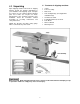
7.0 Assembly Tools need for assembly: 10mm hex wrench (provided) 10-12mm combination wrench (provided) forklift or hoist with straps cross-point screwdriver 1. Remove top and sides of crate from around the machine. 2. Remove the dust hood and the fence assembly from the skid. Reach into the stand and remove the screws securing the stand to the skid. Figure 1 3. Raise the jointer off the skid with lifting straps.
7.2 Switch Arm The arm (Figure 3) on which the push button switch is located is shipped in the down position. The arm should be pivoted to upright position as shown. Tighten the two screws with a 10mm wrench. 7.3 Dust Hood Before attaching the dust hood, make sure the hole in the dust chute is concealed by the dust chute cover, as shown in Figure 4. Mount the dust hood to the jointer stand using the seven 1/4 x 1/2 hex cap screws and seven 1/4 lock washers (Figure 5).
8.1 Voltage Conversion The Model 1285 Jointer is wired for 1-phase, 230 volt only; or 3-phase, 230/460 volt. The 3phase model is pre-wired at the factory for 230 volt. However, if you wish to convert your 3phase jointer from 230 volt to 460 volt, proceed as follows: 1. Disconnect machine from power source. 2. Remove cover from junction box, and open the side door on the stand. 3.
9.0 Adjustments Disconnect jointer from power supply before making adjustments. 9.1 Drive Belt Tension To check the tension of the drive belts: 1. Remove the three cap nuts and flat washers on the pulley cover with a 9/16 wrench, and remove the guard to expose the belts and pulleys. See Figure 9. Figure 9 NOTE: The hex nuts and flat washers on the threaded rods (A, Figure 9) should be left in place; they keep the pulley cover from bending as it is being tightened back into place with the cap nuts. 2.
2. Place a straight edge on the outfeed table and extending over the cutterhead, as shown in Figure 13. 3. Rock the cutterhead slightly so that a knife tip contacts the straight edge. If the knife tip just contacts the straight edge without moving the straight edge, then the outfeed table is at the proper height. If the knife tip pushes up the straight edge, the outfeed table is too low. If the knife tip does not contact the straight edge, the outfeed table is too high. Figure 13 4.
9.3 Setting Infeed Table Height (Depth of Cut) 1. To set the cutting depth, loosen handwheel (A, Figure 17) by turning counterclockwise. 2. Move table adjustment arm (B, Figure 17) up or down to raise or lower infeed table. The pointer (C, Figure 17) shows the depth of cut on the adjoining scale. 3. Tighten handwheel securely (A, Figure 17).
5. It is recommended when replacing knives that you clean the knife slots in the cutterhead. Remove the gib along with the gib screws, and remove the two springs. Clean the cutterhead slot of any debris or dust that might prevent the knife from seating properly. Also clean the gib, gib screws, and springs. Closely inspect the gib screws – if the threads appear worn or stripped, or if the heads are becoming rounded, replace the screws. 6. Re-insert the springs and the gib. 7.
9.5 Replacing Knife Inserts (Helical Cutterhead) Jointer knife inserts are very sharp. Use care and proceed slowly when working with or around the cutterhead. The helical cutterhead is a solid steel design that holds 42 two-sided knife inserts, and two rabbet knife inserts on the outboard end of the cutterhead. Replacing knife inserts is a simple process, and they will seat themselves properly without having to be set with a knife gauge.
9.6 Fence Adjustments The fence (A, Figure 22) tilts backward and forward to 45 degrees. It has a 90-degree stop (B, Figure 22) and a 45-degree stop (C, Figure 22). To tilt fence forward: 1. Loosen the lock handle (D, Figure 22) and tilt the fence forward using the handle (E, Figure 22). NOTE: Lift up slightly on the fence while tilting it, to prevent scratching the table surface. 2. Retighten lock handle (D, Figure 22). Figure 22 To tilt fence backward: 1.
To check and adjust the 45-degree stop: 1. Loosen lock handle (D, Figure 22) and tilt fence until it contacts the 45-degree stop (C, Figure 22). 2. Place a machinist’s protractor or similar device set at 45 degrees on the table and against the fence. 3. If adjustment is necessary, loosen the hex nut on the stop screw (C, Figure 22) and turn the stop screw until the fence is flush with the protractor. 4. Retighten the hex nut. 9.
TIP: If workpieces of the same size are constantly being run on the jointer, the operator may wish to occasionally adjust the fence forward or backward to prevent wear on only one area of the knives. 11.1 Hand Placement At the start of the cut, the left hand holds the workpiece firmly against the infeed table and fence, while the right hand pushes the workpiece toward the knives. After the cut is under way, the jointed surface of the workpiece rests firmly on the outfeed table.
A rabbet cut requires removal of the cutterhead guard. Use extreme caution and keep hands clear of cutterhead. Always replace guard immediately after rabbeting operation is completed. Use push blocks to rabbet cut whenever possible. The rabbeting capacity is 3/4”. 1. Disconnect machine from power source. 2. Set fence for desired width of rabbet. 3. Check width of the rabbet by measuring the distance from the end of a knife in the cutterhead to the fence. 4. Reconnect power.
12.0 Maintenance Disconnect machine from power source before performing any maintenance. Failure to comply may cause serious injury. Check all screws and fasteners occasionally and keep them tightened securely. Inspect cords; a cord that is frayed or damaged in any way should be replaced immediately. The table and fence surfaces must be kept clean and free of rust for best results. Some users prefer a paste wax coating.
6. Slide the cutterhead out the rabbeting side. 7. Loosen hex cap screw (A, Figure 33) and remove pulley (B, Figure 33) and key (C, Figure 33). 8. Loosen screws (D, Figure 33) on both sides and remove bearing cap plates (E, Figure 33). NOTE: Figure 33 shows the pulley end of the cutterhead. The procedure is similar for breaking down the opposite end of the cutterhead – refer to assembly drawing on page 39 for the specific parts.
12.4 Whetting Knives (Straight Cutterhead) When knives become dull enough so that it is noticeable when cutting, they should be resharpened or replaced. A sharp knife will work easier and last longer. The penalty paid for a dull knife is less blade life and greater wear and tear on all parts of the machine. Figure 34 Jointer knives are very sharp. Use care and proceed slowly when working with or around the cutterhead. 1. Disconnect machine from power source. 2.
13.0 Troubleshooting the 1285 Jointer 13.1 Operating Problems Trouble Probable Cause Remedy Finished stock is concave on back end. Knife is higher than outfeed table. Raise outfeed table until it aligns with tip of knife. (see section 9.2) Finished stock is concave on front end. Outfeed table is higher than knife. Lower outfeed table until it aligns with tip of knife. (see section 9.2) Finished stock is concave in the middle. Both tables have too much end fall.
13.2 Mechanical and Electrical Problems Trouble Machine will not start/restart or repeatedly trips circuit breaker or blows fuses. Probable Cause No incoming power. Overload automatic reset has not reset. Jointer frequently trips. Building circuit breaker trips or fuse blows. Motor starter failure. Motor overheated. Motor failure. Miswiring of the unit. On/off switch failure. 24 Remedy Verify unit is connected to power, and on-switch is pushed in completely.
14.0 Optional Accessories 6292535 6400013 PJ1696-011 PJ1285-109B 12” Jointer Knives (set of 3) Carbide Insert Knives for Helical Head (set of 10) Rabbet Inserts for Helical Head (set of 2) Contactor, 3PH, 460V 15.0 Replacement Parts Replacement parts are listed on the following pages. To order parts or reach our service department, call 1-800-274-6848 Monday through Friday (see our website for business hours: www.powermatic.com).
15.1.1 Stand Assembly – Parts List Index No. Part No. Description Size Qty 1............... PJ1285-101 .............Stand .......................................................... ......................................... 1 2............... TS-0680041 .............Flat Washer ................................................. 3/8” ................................... 4 3............... TS-0720091 .............Lock Washer ............................................... 3/8” ...............................
15.1.
15.2.1 Table Assembly – Parts List Index No. Part No. Description Size Qty 1............... 6292525...................Base ............................................................ ......................................... 1 2............... 6292526...................Bar, Table Raising Link................................ ......................................... 2 3............... 6292527...................Bracket ........................................................ .............................
15.2.
15.3.1 Motor Pulley Assembly – Parts List Index No. Part No. Description Size Qty 1............... 6292512...................Motor........................................................... 3HP 3PH .......................... 1 ................. 6292512-MF ............Motor Fan (not shown) ................................ for 3HP 3PH ..................... 1 ................. 6292512-MFC ..........Motor Fan Cover (not shown) ..................... for 3HP 3PH ..................... 1 .................
15.4.1 Cutterhead Guard Assembly – Parts List Index No. Part No. Description Size Qty 1............... 6292581...................Ledge, Rabbet ............................................. ......................................... 1 2............... 6292582...................Guard .......................................................... ......................................... 1 3............... 6292583...................Shaft ........................................................... ..............
15.5.1 Straight Cutterhead Assembly – Parts List Index No. Part No. Description Size Qty ................. 6292550...................Cutterhead Assembly (Items 1 thru 19)……….......................................... 1............... 6292561...................Cutterhead ................................................. ......................................... 1 2............... PJ1696-002 .............Left Bearing Housing ................................... ......................................... 1 3.
15.5.
15.6.1 Helical Cutterhead Assembly – Parts List Index No. Part No. Description Size Qty ................. PJ1285-600 .............Cutterhead Assembly (Items 1 thru 22)……….......................................... 1............... PJ1285-601 .............Cutterhead .................................................. ......................................... 1 2............... PJ1696-002 .............Left Bearing Housing ................................... ......................................... 1 3.....
15.6.
15.7.1 Fence Assembly – Parts List Index No. Part No. Description Size Qty 1............... 6292592...................Support, Fence ............................................ ......................................... 1 2............... 6292593...................Bracket ........................................................ ......................................... 1 3............... 6292594...................Column, Gear .............................................. ...............................
15.7.
16.0 Electrical connections for 1285 Jointer 16.1.
16.1.
427 New Sanford Road LaVergne, Tennessee 37086 Phone: 800-274-6848 www.powermatic.