This .pdf document is bookmarked Operating Instructions and Parts Manual 18-inch Variable Speed Drill Press Model PM2800B Powermatic 427 New Sanford Road LaVergne, Tennessee 37086 Ph.: 800-274-6848 www.powermatic.com Part No.
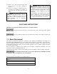
adjusting wrenches are removed from the machine before turning it on. 14. Keep safety guards in place at all times when the machine is in use. If removed for maintenance purposes, use extreme caution and replace the guards immediately after completion of maintenance. 1.0 IMPORTANT SAFETY INSTRUCTIONS 15. Check damaged parts. Before further use of the machine, a guard or other part that is damaged should be carefully checked to determine that it will operate properly and perform its intended function.
28. Remove loose items and unnecessary work pieces from the area before starting the machine. WARNING: Drilling, sawing, sanding or machining wood products generates wood dust and other substances known to the State of California to cause cancer. Avoid inhaling dust generated from wood products or use a dust mask or other safeguards for personal protection. 29. Don’t use in dangerous environment. Don’t use power tools in damp or wet location, or expose them to rain. Keep work area well lighted.
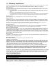
3.0 Warranty and Service Powermatic warrants every product it sells against manufacturers’ defects. If one of our tools needs service or repair, please contact Technical Service by calling 1-800-274-6846, 8AM to 5PM CST, Monday through Friday. Warranty Period The general warranty lasts for the time period specified in the literature included with your product or on the official Powermatic branded website. • Powermatic products carry a limited warranty which varies in duration based upon the product.
4.0 Table of contents Section Page 1.0 IMPORTANT SAFETY INSTRUCTIONS ....................................................................................................... 2 2.0 About this manual .......................................................................................................................................... 3 3.0 Warranty and Service ..................................................................................................................................... 4 4.
5.0 Specifications Model number .................................................................................................................................................. PM2800B Stock number ...................................................................................................................................................1792800B Motor and electricals: Motor type ................................................................................
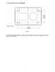
5.1 Base Hole Centers for PM2800B Figure 1 The specifications in this manual were current at time of publication, but because of our policy of continuous improvement, Powermatic reserves the right to change specifications at any time and without prior notice, without incurring obligations.
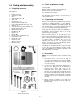
6.2 Tools required for setup: 6.0 Setup and assembly (not provided) 6.1 Shipping contents Rubber mallet (or hammer and wood block) Wrenches: 24,19,17,14 and 10mm 2, 3 and 5mm hex wrenches See Figure 2.
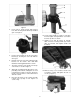
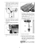
Figure 3 4. Insert shaft of worm through table bracket hole, while meshing worm with the preinstalled gear. See Figure 4. Figure 5 10. Screw locking handle (F, Figure 5) into table bracket. Tighten locking handle to secure table bracket’s position on column. 11. Slightly loosen bolt (G, Figure 6) beneath table, and loosen locking handle (H). Rotate table to horizontal, and retighten handle and bolt (H,G). Figure 4 5.
13. Install three downfeed handles into hub by screwing them in completely, and tightening each nut against hub (Figure 8). A flat is provided on each handle for a wrench to help tighten if needed. NOTE: The downfeed handles can be installed on either side of head. Figure 10 17. Thoroughly clean entire arbor and inside of chuck (Figure 11) with a soft rag and solvent, such as mineral spirits.
dedicated 20 amp circuit with a 20 amp circuit breaker or time-delay fuse marked “D”. When operated on 230 volt power, it is recommended that the drill press be connected to a dedicated 15 amp circuit with a 15 amp circuit breaker or timedelay fuse marked “D”. Local codes take precedence over recommendations. 6.5 Table insert leveling Referring to Figures 12 and 13: 1. Remove two screws beneath table insert (L, Figure 12). 7.1 Grounding instructions 1.
overheating. Table 1 shows correct size to use depending on cord length and nameplate ampere rating. If in doubt, use the next heavier gauge. The smaller the gauge number, the heavier the cord. Ampere Rating More Than Not More Than Volts Total length of cord in feet 120 240 25 50 50 100 100 200 AWG 150 300 00 06 18 16 16 14 Figure 14 06 10 18 16 14 12 3.
3. Tighten column locking handle (A). 8.1.3 Tilt table Referring to Figures 16 and 17: 1. To tilt table, slightly loosen bolt (D) and loosen handle (E). Figure 18 8.3 Changing spindle speeds Change speeds only while drill press is running. With the drill press running, rotate handwheel (shown in Figure 9) until desired speed is displayed on LED readout at front of head. Speed range is 250 to 3000 RPM. Figure 16 2.
Figure 20 8.7 Laser adjustment Referring to Figures 21 through 24: Do not look directly into the laser beam or view it directly with optical instruments. See Figure 21. Figure 19 8.5 Work stop The work stop (G, Figure 19) is used for repetitive drilling in boards of identical length. Flip up the work stop to slide it along the fence or to remove it. Pull it down to tighten in position. 8.
The laser is now calibrated properly and the location of your holes can be centered at the cross hairs for accurate drilling. Figure 22 Vertical Alignment 4. 5. Use the socket head screw (H, Figure 23) located toward front of laser assembly, to adjust verticality of laser line. Turn screw as needed (2.5mm hex wrench), and move board side-to-side as needed, until laser light (E) aligns with board marking (B). Figure 24 9.
10.3 General Inspection Before each operation of your Model 2800B drill press, make a habit of checking that all locking handles, set screws, bolts, etc., are tight on the table and head. Confirm that drill bit is securely inserted inside chuck jaws. Clear all items, such as tools and rags, away from machine. Before attempting regular work, get the feel of the drill press by practicing on scrap material. For best results, always use sharp bits and proper feed rates. 10.
find their way into lumber and make staining and finishing difficult. The quill return spring should receive SAE 20 oil once yearly. Apply the oil beneath the coil spring cover (L, Figure 20) using a squirt can. 11.1 Belt replacement Referring to Figures 26 and 27: If future replacement of belts is needed, proceed as follows: Figure 27 This procedure requires operating machine with pulley cover removed. Keep hands away from moving belts and pulleys. 1. Remove pulley cover using a long shaft screwdriver.
12.0 Troubleshooting the PM2800B Drill Press Table 2 Trouble Drill press will not start (power light is OFF). Drill press will not start (power light is ON). Probable Cause Not connected to power. Fuse blown, or circuit breaker tripped. Cord damaged. Safety key removed. Switch malfunction. Extension cord too light or too long. Drill press does not come up to speed. Low current. Motor or spindle pulley out of balance. Motor malfunction. Motor stalls. Overfeeding the bit. Dull bit.
13.1.
13.1.2 Part List for PM2800B Index No. Part No. Description Size Qty. 1 ................. PM2800B-001 ............. Base ............................................................................. ........................................ 1 2 ................. PM2800-075................ Column Holder ............................................................. ........................................ 1 3 ................. TS-1505061 ................ Hex Socket Head Cap Screw..........................
Index No. Part No. Description Size Qty. 63 ............... TS-1504051 ................ Hex Socket Hd. Cap Screw.......................................... M8x25 ............................. 1 64 ............... PM2800B-064 ............. Collar ........................................................................... ........................................ 1 65 ............... PM2800B-065 ............. Spindle ......................................................................... ................
Index No. Part No. Description Size Qty. 126 ............. PM2800B-126 ............. Rubber Cap.................................................................. ........................................ 1 127 ............. PM2800B-127 ............. LED Seat...................................................................... ........................................ 2 128 ............. PM2800B-128 ............. Heat Sink ..................................................................... ............
Index No. Part No. Description Size Qty. 183 ............. TS-2311061 ................ Hex Nut ........................................................................ M6 ................................... 4 184 ............. PM2800B-184 ............. Locking Cable Tie ........................................................ ........................................ 2 185 ............. PM2800B-185 ............. Nut ............................................................................... M6 .....
14.