
Use and Care Manual


9
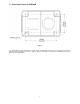
Figure 3
4. Insert shaft of worm through table bracket
hole, while meshing worm with the preinstalled
gear. See Figure 4.
Figure 4
5. Position rack (B, Figure 5) into the slot in table
bracket (C), meshing the rack teeth with the
worm gear.
6. Hold the rack in the slot, while setting the table
bracket over the column. Then slide table
bracket and rack together down the column.
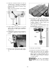
7. The lower end of the rack should rest in the lip
of the holder, as shown in Figure 3.
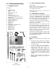
8. Slide table elevating handle (D, Figure 5) onto
protruding shaft of worm, and tighten set screw
in handle with a 3mm hex wrench. Crank the
handle counterclockwise to lower table bracket
down the column.
9. Place ring (E, Figure 5) onto column and slide
it down over top edge of rack. Tighten set
screw on ring.
Figure 5
10. Screw locking handle (F, Figure 5) into table
bracket. Tighten locking handle to secure table
bracket’s position on column.
11. Slightly loosen bolt (G, Figure 6) beneath
table, and loosen locking handle (H). Rotate
table to horizontal, and retighten handle and
bolt (H,G).
Figure 6
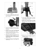
12. With the help of an assistant, mount head
assembly to column, and tighten the two set
screws (J, Figure 7).
Figure 7