
Use and Care Manual

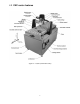

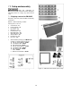
Table Of Contents
- CNC Routers
- 1.0 IMPORTANT SAFETY INSTRUCTIONS
- 1.1 Switch lock-out
- 2.0 About this manual
- 3.0 Table of contents
- 4.0 CNC router features
- 5.0 Specifications for Powermatic CNC Router Machines
- 6.0 Glossary
- 7.0 Setup and assembly
- 7.1 Shipping contents for PM-2X2R
- 7.2 Unpacking and cleanup
- 7.3 Tools required for assembly
- 7.4 Shipping contents for PM-2X4SP
- 7.5 Unpacking and cleanup
- 7.6 Tools required for assembly
- 7.7 Assembling stand (all models)
- 7.8 Installing router table on stand
- 7.9 Completing assembly
- 7.10 Installing router (PM-2X2R only)
- 7.11 Installing top guard
- 8.0 Electrical connections
- 9.0 Setup for operation
- 10.0 Operations
- 11.0 Controller functions
- 12.0 User-maintenance
- 13.0 Additional accessories
- 14.0 Troubleshooting PM-2X2R and PM-2X4SP CNC routers
- 15.0 Replacement Parts
- 15.1.1 PM-2X2R Assembly I – Exploded View
- 15.1.2 PM-2X2R Assembly II – Exploded View
- 15.1.3 PM-2X2R Assemblies – Parts List
- 15.2.1 PM-2X2S Stand Assembly – Exploded View
- 15.2.2 PM-2X2S Stand Assembly – Parts List
- 15.3.1 PM-2X4SP Assembly I – Exploded View
- 15.3.2 PM-2X4SP Assembly II – Exploded View
- 15.3.3 PM-2X4SP Assemblies – Parts List
- 15.4.1 PM-2X4S Stand Assembly – Exploded View
- 16.0 Electrical Connections for CNC Router
- 17.0 Warranty and service
6
15.3.2 PM-2X4SP Assembly II – Exploded View ........................................................................................... 40
15.3.3 PM-2X4SP Assemblies – Parts List .................................................................................................... 41
15.4.1 PM-2X4S Stand Assembly – Exploded View ...................................................................................... 43
15.4.2 PM-2X4S Stand Assembly – Parts List ............................................................................................... 44
16.0 Electrical Connections for CNC Router ...................................................................................................... 45
16.1 Main circuit diagram – model PM-2X2R only ......................................................................................... 45
16.2 Main circuit diagram – model PM-2X4SP only ....................................................................................... 46
16.3 7-Pin Cable Connector ........................................................................................................................... 47
16.4 26-Pin Cable Connector ......................................................................................................................... 48
16.5 Handheld controller connections ............................................................................................................ 49
16.6 Patch board connections ........................................................................................................................ 50
16.7 Patch board I/O descriptions .................................................................................................................. 51
17.0 Warranty and service ................................................................................................................................. 56