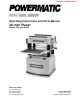
This Manual is Bookmarked Operating Instructions and Parts Manual 20-inch Planer Models 209 and 209HH WMH TOOL GROUP 2420 Vantage Drive Elgin, Illinois 60124 Ph.: 800-274-6848 www.wmhtoolgroup.com Part No.
Warranty and Service WMH Tool Group, Inc., warrants every product it sells. If one of our tools needs service or repair, one of our Authorized Service Center located throughout the United States can give you quick service. In most cases, any of these WMH Tool Group Authorized Service Centers can authorize warranty repair, assist you in obtaining parts, or perform routine maintenance and major repair on your POWERMATIC® tools. For the name of an Authorized Service Center in your area call 1-800-274-6848.
Table of Contents Warranty and Service.................................................................................................................................... 2 Table of Contents.......................................................................................................................................... 3 Warning ......................................................................................................................................................... 4 Introduction ....
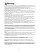
Warning As with all machines, there is a certain amount of hazard involved with the use of this planer. Use the machine with the respect and caution demanded where safety precautions are concerned. When normal safety precautions are overlooked or ignored, personal injury to the operator can result. Read, understand and follow the safety and operating instructions found in this manual. Know the limitations and hazards associated with this machine. Electrical grounding.
Hand safety. Keep hands outside the machine. NEVER reach under the guards to try to clear stock that stops feeding. Do not clear chips and sawdust with hands; use a brush. Do not have any part of the hands under that part of the board that is over the table when starting a cut; the infeed roll will engage the board and force it down against the table causing a pinching action. Do not operate machine while the gear cover is open.
Introduction This manual is provided by WMH Tool Group covering the safe operation and maintenance procedures for a Powermatic Model 209 and 209HH Planer. This manual contains instructions on installation, safety precautions, general operating procedures, maintenance instructions and parts breakdown. This machine has been designed and constructed to provide years of trouble free operation if used in accordance with instructions set forth in this manual.
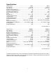
Specifications Model Number.......................................................................209-1 .......................................................209-3 Stock Number ..................................................................1791296 .................................................. 1791297 Table Area (in.) ............................................................25-3/4 x 20 .............................................. 25-3/4 x 20 Maximum Planing Width (in.) .........................
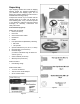
Unpacking Open shipping container and check for shipping damage. Report any damage immediately to your distributor and shipping agent. Do not discard any shipping material until the Planer is assembled and running properly. Compare the contents of your container with the following parts list to make sure all parts are intact. Missing parts, if any, should be reported to your distributor. Read the instruction manual thoroughly for assembly, maintenance and safety instructions.
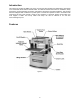
Assembly Tools required for assembly: Forklift or hoist with slings Pliers Open-End Wrenches (10,12,19mm) – provided Hex Wrenches, 4 and 5mm – provided Remove the screws holding the planer to the pallet and use a forklift or hoist to lift the planer off the pallet. Forks and straps should always be placed under the four lifting handles when lifting this machine (Figure 5). The lifting handles can be pushed back in when not in use.
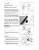
Extension Tables 1. Mount a cast iron table to the edge of the main table with three M8 x 25 hex cap screws (Figure 9) using a 12mm wrench. Do not fully tighten yet. 2. The extension table must be leveled with the main table. Place a straight edge (such as a jointed board) across both tables. 3. Insert three socket set screws with a 4mm hex wrench, and screw them in or out as needed until tables are level. 4. Securely tighten the hex cap screws. Figure 9 5.
Extension Cords Recommended Gauges (AWG) of Extension Cords Extension Cord Length * The use of an extension cord is not recommended for this machine, but if one proves necessary make sure the cord rating is suitable for the amperage listed on the machine's motor plate. An undersize cord will cause a drop in line voltage resulting in loss of power and overheating. The chart in Figure 11 shows the correct size cord to use based on cord length and motor plate amp rating.
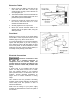
When planing smooth stock the rollers should be set at low position. NOTE: When raising the roller higher above the table, the range is from .003" to .006" (Figure 14). The table rollers are factory set for average planing and are parallel to the table surface. If you desire to adjust the table rollers higher or lower, proceed as follows: 1. Disconnect machine from power source. Figure 14 2. Lay a straight edge across both rollers. 3.
4. If an adjustment to one or more of the knives is necessary, slightly loosen the knife gib (E, Figure 18) by turning the six screws (F, Figure 18) into the gib (i.e. clockwise, when facing the screw heads) with a 12mm hex wrench. Turn the screws just enough to relieve stress in the cutterhead without disturbing the setting of the knives. Do this for all four knives at the same time. 5.
6. Inspect the cutting edge of the knives for nicks or wire edge. Hone the knives slightly using a stone or if the knives are to be sharpened, maintain a cutting angle of 35 degrees. 7. Insert springs, knife and gib into slot of cutterhead. Back out screws just enough to hold the knife in the cutterhead. 8. Place knife setting gauge (Figure 19) over knife. 9.
Work Table Parallel to Cutterhead The work table is set parallel to the cutterhead at the factory and no further adjustment should be necessary. If your machine is planing a taper, first check to see if the knives are set properly in the cutterhead. Then check to see if the work table is set parallel to the cutterhead. Proceed as follows: 1. Disconnect machine from power source. 2. Place the gauge block (Figure 21) on the work table directly under the edge of a knife or knife insert as shown.
Anti-Kickback Fingers The anti-kickback fingers (A, Figure 23) are an important safety feature, as they help prevent kickback of stock. They operate by gravity and should be inspected frequently to make sure they re free of gum and pitch, so that they move independently and operate correctly. Infeed and Outfeed Roller Spring Tension The infeed roller (B, Figure 23) and outfeed roller (F, Figure 23) are those parts of your planer that feed the stock while it is being planed.
Outfeed Roller Height 1. Disconnect machine from power source. 2. Make sure the knives are set properly as previously explained under "Knife Adjustment." 3. Place the gauge block (J, Figure 26) on the table directly beneath the cutterhead (D, Figure 26). 4. Using a 0.02" (0.5mm) feeler gauge (K, Figure 26) placed on top of the gauge block, raise the work table until the knife just touches the feeler gauge when the knife is at its lowest point.
Pressure Bar Height The pressure bar prevents the stock from lifting after it passes under the cutterhead. Check the height of the pressure bar with your gauge block and a .008" (0.2mm) feeler gauge. If adjustment is needed: 1. Remove top cover. 2. Loosen the lock nuts (B, Figure 29) on both ends of the pressure bar and turn the set screws as needed. 3. When the pressure bar contacts the top of the gauge block, tighten the lock nuts (B, Figure 29).
1. Disconnect machine from power source. 2. Remove the three hex cap screws and washers (E, Figure 30). 3. Remove the three sprockets (B, Figure 30) from the infeed roller, outfeed roller and the gear shaft at the same time. 4. When all sprockets have been removed, replace the gear shaft sprocket (G, Figure 31) and its chain (F, Figure 31) with those of a different size. 5. Mount all three sprockets and chains to their shafts, and tighten all hex cap screws and washers (E, Figure 30).
Lubrication Maintenance power source maintenance. The bearings on the cutterhead are factory lubricated and sealed for life – no lubrication is required. Disconnect machine from before performing any GEARBOX LUBRICANT The lubricant in the gear box must be replaced every 2,500 hours. Multi-purpose gear box lubricant will be suitable.
The item numbers on this chart are referenced to the surrounding illustrations. No.
Troubleshooting: Operating Problems Trouble Probable Cause Remedy Table rollers not set properly. Adjust rollers to proper height. Inadequate support of long boards. Support long boards with extension rollers. Uneven feed roller pressure front to back. Adjust feed roller pressure. Dull knives or knife inserts. 209: Sharpen or replace knives. 209HH: Rotate or replace inserts. Lumber not butted properly. Butt end to end each piece of stock as they pass through.
Troubleshooting: Mechanical and Electrical Problems Trouble Uneven depth of cut side to side. Board thickness does not match depth of cut scale. Chain is jumping. Machine will not start/restart or repeatedly trips circuit breaker or blows fuses. Probable Cause Remedy Knife projection from cutterhead is incorrect (209 only) Adjust knife projection. Table not parallel to cutterhead. Adjust table/cutterhead parallelism. Depth of cut scale is incorrect. Adjust depth of cut scale. Inadequate tension.
Trouble Probable Cause Remedy Motor starter failure. Examine motor starter for burned or failed components. If damage is found, replace motor starter. If motor starter looks okay but is still suspect, you have two options: have a qualified electrician test the motor starter for function, or purchase a new starter and establish if that was the problem on changeout.
Cutterhead Assembly 25
Parts List: Cutterhead Assembly Index No. Part No. Description Size Qty 1 ...............6012204 ...................Nut........................................................................ 5/16-18NC .................. 2 2 ...............6292622 ...................Knife Locking Bar * .............................................. .................................... 4 3 ...............6284811 ...................Belt (model 209)................................................... .......................
58 .............6292636 ...................Spring................................................................... .................................... 4 59 .............6292635 ...................Bushing ................................................................ .................................... 4 60 .............6292638 ...................Plate ..................................................................... .................................... 4 61 .............6292658 ...................
Base Assembly 28
Parts List: Base Assembly Index No. Part No. Description Size Qty 1 ...............6292649 ...................Ring, Retaining .................................................... STW-12....................... 1 2 ...............6292742 ...................Gear ..................................................................... 24T.............................. 1 3 ...............6292740 ...................Retaining Ring ..................................................... RTW-38.......................
Gearbox Assembly 30
Parts List: Gearbox Assembly Index No. Part No. Description Size Qty 1 ...............6292788 ...................Socket Head Cap Screw...................................... M6 x 1.0P x 25L.......... 5 2 ...............6292785 ...................Pin ........................................................................ 8 x20 ........................... 2 3 ...............6292787 ...................Cover.................................................................... ................................
Stand Assembly 32
Parts List: Stand Assembly Index No. Part No. Description Size Qty 1 ...............6292807 ...................Strain Relief.......................................................... .................................... 1 2 ...............6292804 ...................Key ....................................................................... .................................... 1 3 ...............6292802 ...................Hex Nut ................................................................ M8 x 1.
Parts List: Table Assembly Index No. Part No. Description Size Qty 1 ...............6292724 ...................Eccentric Shaft..................................................... .................................... 4 2 ...............6292679 ...................Bearing................................................................. 6201Z.......................... 4 3 ...............6292722 ...................Roll ....................................................................... ................
Electrical Connections – Single Phase, 230 Volt only 35
Electrical Connections – 3 Phase, 230 Volt only 36
Electrical Connections – 3 Phase, 460 Volt only 37
Preventive Maintenance Checklist for Model 209 and 209HH Planers [ ] Work area around machine marked off clearly. [ ] Non-skid floor strips in area where operator normally stands. [ ] Inspect entire machine for loose bolts, nuts, screws. Tighten and replace as necessary. [ ] Clean table and cutterhead area, removing sawdust and chips with a soft bristle brush. Remove gum and pitch with oven cleaner. [ ] Lubricate appropriate places with a good grade non-hardening grease.
WMH Tool Group 2420 Vantage Drive Elgin, IL 60124 Phone: 800-274-6848 Website: www.wmhtoolgroup.