WOOD SHAPER Model 29 Instruction Manual & Parts List M-0460218 (800) 274-6848 www.powermatic.
This manual has been prepared for the owner and operators of a Powermatic Model 29 Shaper. Its purpose, aside from machine operation, is to promote safety through the use of accepted correct operating and maintenance procedures. Completely read the safety and maintenance instructions before operating or servicing the machine. To obtain maximum life and efficiency from your shaper and to aid in using the machine safely, read this manual thoroughly and follow all instructions carefully.
TABLE OF CONTENTS SAFETY RULES: General .......................................................................................................................... 4 Specific ......................................................................................................................... 4 RECEIVING THE SHAPER .......................................................................................................................... 6 INSTALLATION .......................................................
! GENERAL SAFETY RULES READ THE MANUAL: Always read the owner's manual carefully before attempting to use the machine. Know the limitations and hazards associated with its use. INSTALLATION: If mounting machine to the floor, use high quality anchor bolts through the mounting holes on the base. If using a mobile base, be sure to lock the wheels. PROTECTION: Take every precaution to protect yourself, others around you, and the machine itself, from improper use.
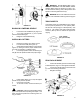
SAFETY LOCK WASHER: Never operate the shaper without the safety locking keyed washer located immediately under the spindle nut, Figure 3. This prevents the nut from coming loose when the spindle is run in a counterclockwise direction. Do not substitute any other type washer in place of the safety lock washer. FIGURE 1 FEED STOCK opposite to the direction of the cutter rotation. Never back stock out of the cutter once the cut has been started.
RECEIVING THE SHAPER Carefully unpack the shaper and any loose items from the wood crate and inspect for damage. Any damage should be reported to your distributor and shipping agent immediately. Before proceeding further, read your manual thoroughly to familiarize yourself with proper assembly, maintenance and safety procedures.
FIGURE 5 3. Mount the dust hood (J) to the rear of the fence body (A) with the four cross screws, Figure 6. FIGURE 7 ADJUSTMENTS BELT ADJUSTMENT/SPEED CHANGE FIGURE 6 MITER GAUGE/CLAMP ASSEMBLY The miter gauge and clamp are used for shaping the end of stock. To assemble the miter gauge: 1. Assemble miter gauge (A) by placing bottom screw into hole on bar (B) and screwing knob and washer onto threaded rod (C), Figure 7. Tighten knob. 2. Slide miter gauge bar into table slot from the end. 3.
FIGURE 11 FIGURE 9 SPINDLE INSTALLATION & REPLACEMENT The Model 29 can use interchangeable spindles as well as router bits. To install the spindle, proceed as follows: 1. Disconnect machine from power source. 2. Lock the main shaft by opening the rear door in the cabinet and pulling out the knob (A), Figure 10, and rotating it to the right until it locks in place. FIGURE 12 6. Unlock the shaft by rotating the lock knob (Figure 10) to the left and allowing it to snap back in. 7.
! WARNING: AFTER INSTALLING A CUTTER AND CHECKING IT FOR TIGHTNESS, CHECK AGAIN! Make certain the direction of cutter is correct and that the stacking collar, safety washer and spindle nut are all tightened securely! ! WARNING: Be sure to release the lock knob from the main shaft before starting machine (Figure 10). TABLE INSERTS FIGURE 13 RAISING & LOWERING SPINDLE 1. Loosen the small handwheel (K), Figure 13. 2. Turn large handwheel (L) until spindle reaches the desired height. 3.
Each half of the aluminum fence should be adjusted as close to the cutterhead as possible without interfering with it. Each can be moved independently depending on the type of work to be done: 4. Loosen the knob (D) on the connection plate and slide aluminum fence (E) to position, Figure 16. Retighten knob (D). WORK HOLD-DOWNS & SAFETY SHIELD Two hold-downs and one safety shield are included with the shaper.
2. When the shaping operation removes the entire edge of the stock, e.g. in jointing or making a full bead, the shaped edge will not be supported by the outfeed fence when both fences are in line, Figure 20a. In this case, the stock should be advanced to the position shown in Figure 20a and stopped. The outfeed fence should then be moved forward to contact the work, Figure 20b. The outfeed fence will then be in line with the cutting circle and the operation can continue.
! CAUTION: When using tenoning cutters with a diameter of 11-13/16" or 9-13/16", run spindle at a speed not higher than 3,000 RPM. If tenoning cutters have a diameter of 7-7/8" or 6- 3/8", run spindle at a speed not higher than 6,000 RPM. If tenoning cutters have a diameter no larger than 3-3/16", run spindle at 10,000 RPM. FIGURE 24 NOTE: It is advisable to place the cutter as low as possible on the spindle to reduce spindle deflection and ensure the best possible finish.
MAINTENANCE 8cT\ ?^bXcX^] 8]cTaeP[ BdXcPQ[T ch_Tb ^U ^X[ 5XV =^ 1 DQR\U ?`U^Y^W 6bUaeU^d\i =QSXY^U ?Y\ "( 2 3_^^USdY_^ @\QdU 6bUaeU^d\i =QSXY^U ?Y\ ") 3 =QY^ CXQVd =_^dX\i CXU\\ 1\fQ^YQ 7bUQcU B" "( FIGURE 27 Apply a drop of light machine oil occasionally on the ledge and wall of the table opening to facilitate the changing of table inserts. The bearings in the motor are sealed for life and do not require lubrication.
Trouble-Shooting for Model 29 Shaper PROBLEM POSSIBLE CAUSE SOLUTION Shaper will not start. 1. Fuse blown or circuit breaker tripped. 2. Cord damaged. 1. Replace fuse or reset circuit breaker. 2. Have cord replaced by authorized service person. Overload kicks out frequently. 1. Extension cord too light or too long. 2. Stock being fed too quickly. 3. Cutter is dull or has gum on it. 1. Replace with adequate size cord. 2. Feed stock more slowly. 3. Clean or replace cutter.
Trouble-Shooting for Model 29 Shaper (continued) PROBLEM POSSIBLE CAUSE SOLUTION Cuts not smooth. 1. Wrong R.P.M. 2. Feed too fast. 3. Working against grain. 4. Cutting too deep. 1. Use faster speed. 2. Pass stock more slowly. 3. Work with grain whenever possible. 4. On very deep cuts make several passes. Spindle does not raise freely. 1. Sawdust and dirt in raising mechanisms. 1. Brush or blow out loose dust and dirt.
PARTS LIST: Fence Assembly (29 Shaper) (6293192 - Items 1 thru 18 & 35 thru 54) NO. PART NO. DESCRIPTION NO. PART NO. DESCRIPTION 1 2 3 4 5 6 7 8 9 10 11 12 13 14 15 16 17 18 19 20 21 22 23 24 25 26 27 28 CHUTE, DUST SCREW, HEX. SOC. SET M8 X 20 KNOB, ADJUSTMENT PLATE SCREW, ADJ. RAM HANDLE, LOCK WASHER CAP, R.H. BLOCK, R.H. BLOCK, L.H. SCREW, HEX. SOC. HD. M6 X 30 FENCE, R.H. FENCE, L.H. GUIDE CAP, L.H.
Fence Assembly (29 Shaper) 17
PARTS LIST: Spindle Assembly (29 Shaper) NO. PART NO. DESCRIPTION NO. PART NO. DESCRIPTION 1 NUT, 3/4" SPINDLE NUT, 1" SPINDLE NUT, 1-1/4" SPINDLE WASHER, KEYED SET, SPACER 3/4" SET, SPACER 1" SET, SPACER 1-1/4" NUT, RETAINER NUT, COLLET BUSHING, 1/4" CHUCK, 1/2" COLLET SPINDLE, INTERCHANGEABLE 3/4" SPINDLE, INTERCHANGEABLE 1" SPINDLE, INTERCHANGEABLE 1-1/4" SCREW, HEX. SOC. HD. M5 X 16 10 11 12 13 14 15 16 17 18 19 20 21 PLATE BEARING KEY, 6 X 54 RING, RETAINING SPINDLE SPRING, DISK, 61.5 X 40.
Spindle Assembly (29 Shaper) 19
PARTS LIST: Shaper Body & Mitre Gauge Assemblies (29 Shaper) NO. PART NO. DESCRIPTION NO. PART NO. DESCRIPTION 1 2 3 4 5 6 7 8 10 11 12 13 14 15 16 17 18 19 20 21 22 23 24 25 26 27 28 29 30 31 32 33 34 35 36 37 38 RING, INSERT RING, INSERT SCREW, HEX. SOC. HD. M5 X 12 SCREW, HEX. SOC. HD. M5 X 16 RING, INSERT TABLE WASHER, M12 CABINET SCREW, HEX. SOC. M12 X 45 COVER, SWITCH PANEL SCREW, CHEESE HD., M4 X 10 BUTTON, START BUTTON, STOP LAMP, PILOT SWITCH, FWD.-REV. HANDLE LATCH LABEL LABEL NUT, HEX.
Shaper Body & Mitre Gauge Assemblies (29 Shaper) 21
PARTS LIST: Tilting Frame Assembly (29 Shaper) NO. PART NO. DESCRIPTION NO. PART NO.
Tilting Frame Assembly (29 Shaper) 23
ELECTRICAL SCHEMATIC: Model 29 Tilting Shaper THREE PHASE Y- D START (2-STEP SWITCH) PAR T N O. 24 D ESC R IPTION TYPE SPEC IFIC ATION 6293074 FOR-REV SWITC H CS 25A 1a 6293072 STOP PB1 10A 250VAC 1b 6293071 START PB2 10A 250VAC 1a 6292977 MAGNETIC C ONTAC TOR MC 1 MA15 6292976 THERMAL RELAY O.L.
ELECTRICAL SCHEMATIC: Model 29 Tilting Shaper THREE PHASE 24V PAR T N O. D ESC R IPTION TYPE SPEC IFIC ATION 6293200 C ONTROL C IRC UIT TRANSFORMER Tr. PT54 6293074 FOR-REV SWITC H CS 25A 1a 6293072 STOP PB1 10A 250VAC 1b 6293071 START PB2 10A 250VAC 1a 6292974 MAGNETIC C ONTAC TOR MC 1 MA15 24VAC 6292976 THERMAL RELAY O.L.
OPTIONAL ACCESSORIES Model 29 Tilting Shaper 6293198 6293199 6293200 26 1" Spindle Assembly, 6" under the nut. 1-1/4" Spindle Assembly, 6" under the nut. 460V transformer.
To order parts or reach our service department, please call our toll-free number between 8:00 a.m. and 4:30 p.m. (CST), Monday through Friday. Having the Model Number and Serial Number of your machine available when you call will allow us to serve you quickly and accurately. Locating the stock number of the part(s) required from your parts manual will also expedite your order. Phone No.: (800) 274-6848 Fax No.
04/01 JET Equipment & Tools P.O. Box 1349 Auburn, WA 98071-1349 Phone: (800) 274-6848 Fax: (800) 274-6840 E-mail: powermatic@powermatic.com Website: www.powermatic.