Operating Instructions and Parts Manual 3-Roll Powered Stock Feeder Model PF3-JR WMH TOOL GROUP, Inc. 2420 Vantage Drive Elgin, Illinois 60123 Ph.: 800-274-6848 www.powermatic.com Part No.
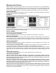
Warranty and Service WMH Tool Group, Inc., warrants every product it sells. If one of our tools needs service or repair, one of our Authorized Service Centers located throughout the United States can give you quick service. In most cases, any of these WMH Tool Group Authorized Service Centers can authorize warranty repair, assist you in obtaining parts, or perform routine maintenance and major repair on your POWERMATIC® tools. For the name of an Authorized Service Center in your area call 1-800-274-6848.
Table of Contents Warranty and Service .............................................................................................................................. 2 Warning................................................................................................................................................... 4 Introduction ............................................................................................................................................. 6 Description ..................
Warning 1. Read and understand the entire owners manual before attempting assembly or operation. 2. Read and understand the warnings posted on the machine and in this manual. Failure to comply with all of these warnings may cause serious injury. 3. Replace the warning labels if they become obscured or removed. 4. This stock feeder is designed and intended for use by properly trained and experienced personnel only.
21. Make your workshop child proof with padlocks, master switches or by removing starter keys. 22. Give your work undivided attention. Looking around, carrying on a conversation and “horse-play” are careless acts that can result in serious injury. 23. Maintain a balanced stance at all times so that you do not fall or lean against moving parts. Do not overreach or use excessive force to perform any machine operation. 24. Use the right tool at the correct speed and feed rate.
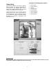
Introduction This manual is provided by WMH Tool Group, Inc., covering the safe operation and maintenance procedures for a Model PF3-JR Stock Feeder. This manual contains instructions on installation, safety precautions, general operating procedures, maintenance instructions and parts breakdown. This machine has been designed and constructed to provide years of trouble free operation if used in accordance to instructions set forth in this manual.
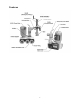
Features 7
Contents of the Shipping Container Unpacking 1 1 2 1 1 1 1 1 Open shipping container and check for shipping damage. Report any damage immediately to your distributor and shipping agent. Do not discard any shipping material until the Stock Feeder is assembled and running properly. Compare the contents of your container with the following parts list to make sure all parts are intact. Missing parts, if any, should be reported to your distributor.
Assembly and Installation Tools needed for assembly: 5mm hex wrench 12mm and 14mm open end wrenches Remove the clear plastic from around the feeder and stand. Exposed metal surfaces have been given a protective coating at the factory. This should be removed with a soft cloth moistened with a good commercial solvent, such as kerosene or mineral spirits. Do not use acetone, gasoline, or lacquer thinner for this purpose.
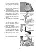
6. Place the base over the hole pattern. Align the four holes of the base with the holes in the mounting surface. Make sure the lock handle is positioned in a convenient place before tightening the base to the mounting surface. 7. Insert four M10 screws (not provided) through the holes of the base and into the holes on the mounting surface. See Figure 2. Tighten screws securely. 8. The stand assembly can be oriented with either of the columns in horizontal or vertical position.
Grounding Instructions Electrical connections must be made by a qualified electrician in compliance with all relevant codes. This machine must be properly grounded to help prevent electrical shock and possible fatal injury. This Stock Feeder must be grounded. In the event of a malfunction or breakdown, grounding provides a path of least resistance for electric current to reduce the risk of electric shock.
The green colored rigid ear, lug, or tab, extending from the adapter, must be connected to a permanent ground such as a properly grounded outlet box, as shown in Figure 7. Recommended Gauges (AWG) of Extension Cords Extension Cord Length * Make sure the voltage of your power supply matches the specifications on the motor plate of the machine. Extension Cords If an extension cord is necessary make sure the cord rating is suitable for the amperage listed on the machine's motor plate.
3. Loosen lock handle (B, Figure 10) and rotate the swivel cone (C, Figure 10) 180degrees, as shown in Figure 10. 4. Re-tighten lock handle (B, Figure 10). 5. Loosen lock handle (D, Figure 10) and rotate the arm cone as needed until it can slide back onto the horizontal arm. Tighten locking handle (D, Figure 10). 6. Mount the Stock Feeder to the horizontal arm and tighten the screw (A, Figure 10).
Operating Controls The control switch (Figure 14) turns the motor on, and also determines its direction – forward or reverse. If a jam should occur while feeding a workpiece, DO NOT turn the stock feeder to reverse while the auxiliary machine is still running in forward direction. If a workpiece becomes jammed, turn off both the auxiliary machine and the stock feeder. Raise the feeder in order to clear the workpiece. Then reset the feeder height and begin the feed over again.
6. When used in normal horizontal position, the stock feeder should be adjusted for height so that the distance between the table and the feed rollers is approximately 1/8” to 3/16” (3 to 5mm) less than the thickness of the workpiece. See Figure 15. Although the stock feeder when properly used will greatly reduce the chance of workpiece kickback, there is still a potential for kickback. Never stand directly in the path of the workpiece as it passes under the Stock Feeder rollers.
When Used with a Table Saw 1. Position the Stock Feeder so that the axis of the saw blade lines up between the center roller and infeed roller. See Figure 18. This will allow the Stock Feeder to grip the offcut of the workpiece as it leaves the blade. 2. Rotate the Stock Feeder so that the direction of feed is angled slightly toward the fence by approximately 3/16” (5mm); that is, the outfeed roller should be slightly closer to the fence than the infeed roller. See Figure 18.
The mating parts of the arm cone and swivel cone should be kept clean. See Figure 21. When disassembling any of the cones from the stock feeder, wipe off both mating parts with a clean rag before re-assembling. NOTE: These cones are subject to high torques and it may be necessary to periodically re-tighten the lock handles until the cone surfaces become securely seated. Figure 21 Lubrication Gearbox The Stock Feeder is shipped with oil installed in the gearbox.
Chains Lubricate the drive chains (Figure 24) with good quality all-purpose grease every 3 months, or more frequently if needed. Figure 24 Lead Screws Occasionally apply a light coat of grease to the lead screw of the vertical column, and to the lead screw of the horizontal arm. See Figure 25.
Troubleshooting Trouble Probable Cause Remedy Not connected to power source. Check plug connection. Fuse blown, or circuit breaker tripped. Replace fuse, or reset circuit breaker. Cord damaged. Replace cord. Starting capacitor bad. Replace starting capacitor. Wrong gears installed for the desired feed rate. Install correct gears in proper positions. [page 13] Extension cord too light or too long. Replace with adequate size and length cord. [page 12] Low current from electrical supply.
Parts List: PF3-JR Stand Assembly Index No. Part No. Description Size Qty 1............... PF3JR-101 ..............Base...................................................................................................... 1 2............... TS-1550061 .............Flat Washer........................................................M8.............................. 1 3............... PF3JR-103 ..............Lock Handle ........................................................................................
PF3-JR Stand Assembly 21
Parts List: PF3-JR Stock Feeder Index No. Part No. Description Size Qty 1............... PF3JR-201 ..............Oil Cap .................................................................................................. 1 2............... PF3JR-202 ..............“O” Ring ................................................................................................ 1 3............... PF3JR-203 ..............Sprocket Case...................................................................................
PF3-JR Stock Feeder 23
PF3-JR Electrical Connections 24
Boring Template SCALE 1:1 Cut out and tape into place on mounting surface.
NOTES 26
WMH Tool Group, Inc. 2420 Vantage Drive Elgin, Illinois 60124 Phone: 800-274-6848 www.powermatic.com www.wmhtoolgroup.