This .pdf document is bookmarked Operating Instructions and Parts Manual 35” x 20” Woodturning Lathe Model 3520C Powermatic 427 New Sanford Road LaVergne, Tennessee 37086 Ph.: 800-274-6848 www.powermatic.com Part No.
12. Make all machine adjustments or maintenance with the machine unplugged from the power source. 13. Remove adjusting keys and wrenches. Form a habit of checking to see that keys and adjusting wrenches are removed from the machine before turning it on. 1.0 IMPORTANT SAFETY INSTRUCTIONS 14. Keep safety guards in place at all times when the machine is in use. If removed for maintenance purposes, use extreme caution and replace the guards immediately after maintenance is complete.
28. Use proper extension cord. Make sure your extension cord is in good condition. When using an extension cord, use one heavy enough to carry the current your product will draw. An undersized cord will cause a drop in line voltage resulting in loss of power and overheating. Sect. 7.3, Table 2 shows correct size to use depending upon cord length and nameplate ampere rating. If in doubt, use the next heavier gauge. The smaller the gauge number, the heavier the cord. 34.
3.0 Table of Contents 1.0 IMPORTANT SAFETY INSTRUCTIONS ....................................................................................................... 2 2.0 About this manual .......................................................................................................................................... 3 3.0 Table of Contents ........................................................................................................................................... 4 4.0 Specifications ....
4.
Dimensions Overall size assembled LxWxH Distance floor to spindle centerline (adjustable using levelers) Bed gap Footprint of stand Tool support post diameter Riser block height Weights Net weight Shipping weight 69-1/2 x 34 x 36-1/2 x 47 in. (+4 in. riser block) [1766 x 92 x 119 cm (+10 cm riser block)] 40-5/8 in. (103 cm) +4 in/10cm riser block) 2.5 in. (63.5 mm) 51-3/4”L x 24”W (1315 x 610 mm) 1” (25.4mm) 4” (102 mm) 726 lb. (330 kg) 770 lb. (350 kg) 1 subject to local/national electrical codes.
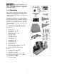
Read and understand the entire contents of this manual before attempting set-up or operation! Failure to comply may cause serious injury. 5.0 Unpacking Open shipping container and check for shipping damage. Report any damage immediately to your distributor and shipping agent. Do not discard any shipping material until the Lathe is assembled and running properly. Compare the contents of your container with the following parts list to make sure all parts are intact.
6.0 Assembly 8. The Lathe should be located in a dry area, on a sturdy floor, and with sufficient lighting. Leave plenty of space around the machine for operations and routine maintenance work. 9. Exposed metal areas of the Lathe, such as bed ways and spindles, have been factory coated with a protectant. This should be removed with a soft cloth and a cleaner-degreaser. Clean the bed areas under headstock, tailstock and tool support base.
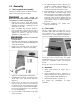
Figure 6-5: optional guard tilted back Figure 6-3: installing brackets 6.5 Bed extension (optional accessory) 6.4 Guard (optional accessory) An optional guard, stock number 6294728, is available for the Lathe (see your Powermatic dealer). To mount guard to Lathe: An optional 20” bed extension assembly, stock number 1353002, is available for the Lathe (see your Powermatic dealer). To mount bed extension to Lathe: 1. 1. Slide tailstock away from edge of bed. 2.
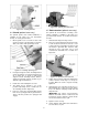
7. Unscrew stop bolt from Lathe bed (Figure 6-6), and screw it into hole at end of bed extension. For outboard turning, where headstock is moved to opposite end of Lathe to accommodate large bowl blanks, the 20” bed extension can be mounted to the four lower holes on Lathe frame. Install the extension post (included with optional bed extension) into the tool rest base. See Figure 6-7. For large outboard work, an optional outboard turning stand (# 6294732) is available – see sect. 16.4.1.
5. Cut the dowel rods to length with a miter saw or hand saw, so that after insertion the rods will be flush with the back of the rear 2x6. 6. Insert the dowel rods through the holes in the rear 2x6, as shown in Figure 6-10. 7. A strip of wood can be screwed to the rear 2x6 to cover the dowel holes and prevent the dowels from working out. During wiring of the Lathe, make sure the fuses have been removed or the breaker has been tripped in the circuit to which the Lathe will be connected.
Figure 8-2: cam adjustment 8.5 Ball bearing live center The live center cap, shown in Figure 8-3, screws clockwise onto the threads of live center body. To remove cap from live center, first insert live center pin through hole in the live center body as shown in Figure 8-3. If pin will not insert at first, rotate cap until pin can be inserted. The cap can now be removed by holding the body stationary while unscrewing cap. Figure 8-1: headstock, tailstock, tool support 8.
4. Screw index pin (G) into headstock to lock spindle. 5. Cut first flute in workpiece. 6. Push index position button (F) to set engaged index position at zero. 7. Unscrew index pin (G) to release spindle, then rotate workpiece until next desired hole shows on readout. 8. Engage index pin, and rout second flute. Continue process. Figure 8-5: center removal Example: If 6 evenly-spaced flutes are needed around full workpiece circumference, use positions 0, 8, 16, 24, 32, and 40. 8.7.
3. Mount spur center with the spindle blank that will be turned. Loosen tailstock locking handle, and slide tailstock until live center is about 1inch from spindle blank, then tighten locking handle. Advance live center using tailstock handwheel, until live center is secured in spindle blank. 4. Mount reference spindle between comparator centers, as shown in Figure 8-7. NOTE: Reference spindle should be mounted last after all adjustment of tailstock and quill has been accomplished with spindle blank.
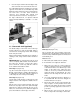
Figure 8-10: sensor and spindle lock collars Figure 8-9: sheave/belt alignment 8.12 Sheave/drive belt replacement IMPORTANT: Replacing the spindle sheave or belt can be a difficult procedure. If you do not feel confident performing this action, take the headstock to an authorized Powermatic service center. 1. Disconnect lathe from power source. 2. Loosen lock handle (J, Figure 8-9) and lift up handle (K) to raise motor. 3. Tighten lock handle (J) to hold motor in raised position.
8.13 Checking spindle play power is restored. Cycle the on/off switch in order to restart the machine. The spindle bearing has been set at the factory for general turning applications. There should be no "end play" or looseness along the spindle’s axis. If any looseness should occur, it may be rectified by carefully tightening the bearing lock nut on the spindle, as follows.
Also, a braking feature eliminates long coasting periods after the Lathe is turned off. Skews – 1-1/2" and 1" or 1-1/4", used to make finishing cuts and details. The 2 horsepower motor is specially designed for use with inverter drives, and is balanced to reduce noise and minimize vibration. Large Roughing Gouge – 1" to 1-1/4", used to eliminate waste wood. Spindle Gouges – 1/4", 3/8", 1/2", used to turn beads, coves and other details. The A.C.
For best results, use a slow speed grinder (1800 rpm) fitted with a 60-grit aluminum oxide wheel (for shaping) and a 100-grit alum. oxide wheel (for final sharpening and touchup). The grinder should be located near your lathe and at a comfortable height. A diamond dresser will keep the wheels true and eliminate glazing. Never allow the tool to rest in one place on the wheel; keep it moving and use a light touch. Carbon steel tools can overheat easily and should be cooled frequently.
The tailstock ram is capable of exerting excessive pressure against the workpiece and the headstock. Apply only sufficient force with the tailstock to hold the workpiece securely in place. Excessive pressure can overheat center bearings and damage both workpiece and Lathe. 10. Move tool support into position. It should be parallel to the workpiece, just below the centerline and approximately 1/8" to 1/4" from the corners of the workpiece to be turned, as in Figure 10-5. Tighten support base to Lathe bed.
Sanding and Finishing Leaving clean cuts will reduce the amount of sanding required. Move the tool support out of the way, adjust the lathe to a low speed, and begin with fine sandpaper (120 grit or finer). Coarser sandpaper will leave deep scratches that are difficult to remove, and dull crisp details on the spindle. Progress through each grit without skipping grits (for example, do not jump from 120 grit to 220 grit).
NOTE: When using a waste block, be careful with the adhesive you select. Dry workpieces can be bonded with ordinary white or yellow glue but must be clamped to ensure a good bond. Green workpieces require cyanoacrylate type glue. As you turn bowls from green wood, make sure you maintain a consistent wall thickness throughout the piece. Leaving a piece thick in some areas and thin in others will cause the wood to dry unevenly and promote checks and cracks. 10.4.
7. As the bowl takes shape, work on the bottom (tailstock end) to accomodate attaching a face plate. 8. Turn a short tenon (about 1/8" long) the size of the hole in the faceplate. See Figure 10-10. This will allow centering the workpiece when the faceplate is attached. Figure 10-11 6. Figure 10-10 9. (NOTE: If you plan to use a chuck, turn a tenon of the appropriate length and diameter to fit your chuck.
3. 4. 5. Remove sanding dust with tack rags or compressed air and, with lathe turned off, apply first coat of finish. Let stand for several minutes, wipe off excess. Allow to dry before sanding again with 320 or 400 grit sandpaper. Clean any rust spots that may develop on the bed with a commercial rust remover. Use compressed air or a vacuum in the headstock interior, in order to keep sawdust and chips from accumulating on belts and sheaves. Also blow off debris that accumulates on the inverter.
12.0 Optional Accessories Below are some of the accessory items available for your 3520C lathe. These items are purchased separately; contact your Powermatic dealer for more information.
13.0 Troubleshooting 3520C Lathe Trouble Probable Cause Remedy Motor fails to develop full power. Power line overloaded. Correct overload condition. Undersize wires in power supply system. Increase supply wire size. Faulty inverter. Contact Powermatic Technical Service. Motor or spindle stalls or will not start. Excessive vibration. Lathe runs at one speed only. Tools tend to grab or dig in. Worn motor. Replace motor. Excessive cut. Reduce depth of cut.
14.0 Recommended lathe speeds (per diameter of workpiece) Diameter of Work Roughing RPM General Cutting RPM Finishing RPM Under 2” 1520 3000 3000 2” to 4” 760 1600 2290 4” to 6” 510 1080 1500 6” to 8” 380 810 1125 8” to 10” 300 650 900 10” to 12” 255 540 750 12” to 14” 220 460 640 14” to 16” 190 400 560 16” to 20” 175 325 450 20” to 24” 175 260 375 Table 3 15.0 Replacement parts Replacement parts are listed on the following pages.
15.1.
15.1.2 3520C Headstock Assembly – Parts List Index No. Part No. Description Size Qty 1 ................ 6294725 .................... Spur Center ............................................................. MT2 ............................... 1 2 ................ 6294736 .................... Faceplate (includes #17 and 102) ........................... 1-1/4-8, Ø 3” ................. 1 3 ................ 6295796 .................... Nylon Insert Socket Set Screw ................................
Index No. Part No. Description Size Qty 61 .............. SR-6P3...................... Strain Relief ............................................................. SR-6P3 ......................... 1 62 .............. TS-081C062 .............. Phillips Pan Head Machine Screw ........................... #10-24x1"...................... 4 63 .............. JWL1642-169 ............ Braking Resistor ...................................................... ...................................... 1 64 .............
15.2.1 3520C Remote Control Box Assembly – Exploded View 15.2.2 3520C Remote Control Box Assembly – Parts List Index No. Part No. Description Size Qty 41 .............. 3520C-141 ................ Remote Control Box Assembly (includes # 41-1 thru 41-18).......................... 1 41-1 ........... 4224B-148................. Switch Fwd /Rev ...................................................... ...................................... 1 41-2 ........... 3520C-1412 .............. Digital Readout Display ...
15.3.1 Spindle Centers Knockout Assembly – Exploded View 15.3.2 Spindle Centers Knockout Assembly – Parts List Index No. Part No. Description Size Qty 82 .............. 6294754 .................... Knockout Rod Assembly (includes # 82-1 thru 82-7) ..................................... 1 82-1 ........... TS-0270031 .............. Socket Set Screw .................................................... 5/16-18x3/8” .................. 1 82-2 ........... 3520B-287................. Slide Hammer ...............
15.4.
15.4.2 Bed, Banjo and Tailstock Assembly – Parts List Index No. Part No. Description Size Qty 1 ................ 3520B-140................. Powermatic Nameplate............................................ ...................................... 1 2 ................ 3520C-202 ................ Backer Plate ............................................................ ...................................... 1 3 ................ TS-0207071 .............. Socket Head Cap Screw ..................................
15.5.1 Stand Assembly – Exploded View 15.5.2 Stand Assembly – Parts List Index No. Part No. Description Size Qty 1 ................ 3520C-301 ................ Stand ....................................................................... ...................................... 2 2 ................ TS-0680042 .............. Flat Washer ............................................................. 3/8"................................ 8 3 ................ TS-0720091 .............. Lock Washer ..............
15.6 Optional Accessories: #6294732, Outboard Turning Stand Index No. Part No. Description Size Qty. .................. 6294732 .................... Heavy Duty Outboard Turning Stand Assembly (items 1 thru 7) ...................... 1 ................ 3042503 .................... Turning Stand Base ........................................................................................ 1 2 ................ 6295897 .................... Offset Tool Support Pin ..............................1.
15.7 Optional Accessories: Bed Extension, Face Plate, Tool Supports, Guard Index No. Part No. Description Size Qty. .................. 1353002 .................... 20” Bed Extension Kit (includes #1 thru 6) .............. ........................................ 1 ................ 3520B-310................. Extension Post ......................................................... ...................................... 1 2 ................ 6294763 .................... Locking Handle ......................
15.8 Optional Accessories: #6294721, Tailstock Swing Away Index No Part No Description Size Qty 1 ................. .................................... Front Plate ................................................................... ........................................ 1 2 ................. PMSA-102 ................... Pivot Pin ....................................................................... ........................................ 1 3 ................. PMSA-103 ...................
15.9.
15.9.2 Optional Accessories: #6294901, Lamp Holder Set – parts list Index No Part No Description Size Qty .................. 6294901 .................... Lamp Holder Set (includes #1 thru 25) .................... ...................................... 1 1 ................ 4224B-301................. Support Tube ........................................................... ...................................... 1 2 ................ 4224B-302................. Lamp Holder ....................................
16.0 Electrical connections for #1353001 – 3520C Lathe 16.
16.
17.0 Warranty and Service Powermatic® warrants every product it sells against manufacturers’ defects. If one of our tools needs service or repair, please contact Technical Service by calling 1-800-274-6846, 8AM to 5PM CST, Monday through Friday. Warranty Period The general warranty lasts for the time period specified in the literature included with your product or on the official Powermatic branded website. • Powermatic products carry a limited warranty which varies in duration based upon the product.
This page intentionally left blank.
427 New Sanford Road LaVergne, Tennessee 37086 Phone: 800-274-6848 www.powermatic.