This Manual is Bookmarked Operating Instructions and Parts Manual Heavy-Duty Mortiser Model 720HD WMH TOOL GROUP, Inc. 2420 Vantage Drive Elgin, Illinois 60124 Ph.: 800-274-6848 www.wmhtoolgroup.com Part No.
Warranty and Service WMH Tool Group, Inc., warrants every product it sells. If one of our tools needs service or repair, one of our Authorized Service Centers located throughout the United States can give you quick service. In most cases, any of these WMH Tool Group Authorized Service Centers can authorize warranty repair, assist you in obtaining parts, or ® perform routine maintenance and major repair on your POWERMATIC tools. For the name of an Authorized Service Center in your area call 1-800-274-6848.
Table of Contents Table of Contents.......................................................................................................................................... 3 Warning ......................................................................................................................................................... 4 Introduction ...................................................................................................................................................
Warning 1. Read and understand the entire owner's manual before attempting assembly or operation. 2. Read and understand the warnings posted on the machine and in this manual. Failure to comply with all of these warnings may cause serious injury. 3. Replace the warning labels if they become obscured or removed. 4. This mortiser is designed and intended for use by properly trained and experienced personnel only.
21. Maintain a balanced stance at all times so that you do not fall or lean against the auger and chisel or other moving parts. Do not overreach or use excessive force to perform any machine operation. 22. Use the right tool at the correct speed and feed rate. Do not force a tool or attachment to do a job for which it was not designed. The right tool will do the job better and safer. 23. Use recommended accessories; improper accessories may be hazardous. 24. Maintain tools with care.
Introduction This manual is provided by WMH Tool Group, Inc. covering the safe operation and maintenance procedures for a Model 720HD Heavy-Duty Mortiser. This manual contains instructions on installation, safety precautions, general operating procedures, maintenance instructions and parts breakdown. This machine has been designed and constructed to provide years of trouble free operation if used in accordance with instructions set forth in this manual.
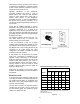
Contents of the Shipping Container Unpacking 1 1 1 1 3 Remove all crating and plastic from around the Mortiser. Check for shipping damage; report any damage immediately to your distributor and shipping agent. Do not discard any shipping material until the Mortiser is assembled and running properly. Open the cabinet rear door and remove any boxes and accessory items. Compare these with the following parts list to make sure all parts are intact.
Assembly Tools required for assembly forklift or hoist with straps/slings 14mm wrench (provided) 4 and 6mm hex wrenches (provided) 1. Remove the four screws that secure the Mortiser to the wood pallet, using a 14mm wrench. 2. With a forklift or hoist, lift the machine off the pallet and into its desired location. 3. The Mortiser should be located in a dry area, on a sturdy, level floor, and with sufficient lighting. Leave plenty of space around the machine for operations and routine maintenance work. 4.
Installing Bushing, Chisel and Auger 1. The mortiser should be disconnected from power source. 2. Open the chuck access cover (A, Figure 3). 3. Insert a bushing (B, Figure 3) into the hole with the bushing’s hole facing the front toward the set screw (C, Figure 3). NOTE: The Mortiser is shipped with the 5/8” bushing pre-installed.) 4. Tighten the set screw (C, Figure 3) with a 4mm hex wrench just enough to hold bushing in place. 5.
This machine must be grounded. In the event of a malfunction or breakdown, grounding provides a path of least resistance for electric current to reduce the risk of electric shock. Improper connection of the equipmentgrounding conductor can result in a risk of electric shock. The conductor, with insulation having an outer surface that is green with or without yellow stripes, is the equipmentgrounding conductor.
Adjustments Squaring Table To Chisel 1. Place a square upon the table and against the chisel, as shown in Figure 6. 2. If the table and chisel are not perpendicular to each other, loosen the table’s stud with the attached hex wrench (A, Figure 6). 3. Loosen the locking handle (B, Figure 6) and adjust the table until the table and chisel are square. 4. Re-tighten the stud (A, Figure 6) and locking handle (B, Figure 6). Figure 6 5. Make sure the pointer aligns with zero on the scale.
Chuck Extension Adaptor The provided Chuck Extension Adaptor is used to lower the chuck for use with after-market chisels (chisels other than those supplied with your machine) that may require a spacer due to varying lengths in shanks. 1. To install the adaptor, first remove the chisel and auger. 2. It may be necessary to remove the bushing to provide enough clearance when installing the chuck and adaptor. If so, loosen the set screw and remove the bushing. 3.
Lateral (X Axis) Use the handle (A, Figure 12) to move the head right or left. The lateral stops should be set in accordance with the length of the mortise cut (see “Setting Lateral Stops”). Up/Down (Z Axis) Handle B, Figure 12. Forward/Backward (Y Axis) Loosen the Y-Axis locking handle (shown in Figure 18) and move the handle (C, Figure 12). NOTE: When making lateral cuts the Y-Axis locking handle (Figure 18) should be tightened.
Chisel Parallel to Workpiece For accurate mortise cuts, the chisel must be parallel to the workpiece. The workpiece should be cut square for this adjustment to be accurate. Check and adjust this parallelism as follows: 1. Move the head forward far enough that the workpiece can be inserted between fence and chisel. 2. Slightly loosen the set screw to allow the chisel to be rotated. 3. Move the head back carefully until the face of the chisel rests against the workpiece, but do not force. See Figure 15.
Gib for Front-to-Back Movement 1. Remove the two screws on the pleated dust cover (F, Figure 18) and move the dust cover out of the way. 2. Loosen the three hex nuts (G, Figure 18) with a 10mm wrench. 3. Turn the three set screws (H, Figure 18) with a 3mm hex wrench, until play is eliminated on the gib (J, Figure 18). 4. Re-tighten the three hex nuts (G, Figure 18) NOTE: Hold the set screws so they do not turn during the tightening process. 5.
Operation General operating procedure: 1. Position workpiece on table and secure with clamp. 2. Set depth stop. 3. For lateral cuts, adjust positive stops according to length of cut. 4. Position head front-to-back and laterally for the first cut. If making a lateral cut, make sure the Y-axis locking handle is tightened. 5. Turn on the machine and feed the chisel and bit steadily into the workpiece.
Sharpening Chisel and Auger The chisel and auger should be kept sharp for best performance. If cutting operations require excessive force, the chisel and/or auger are probably dull and should be sharpened. Blunt edges will give inaccurate mortises and can lead to overheating and breakage of chisel or auger. If chisel and auger are badly worn and become difficult to sharpen, they should be replaced. Chisel Sharpen the chisel with a mortise chisel cutter with the correct size pilot.
Troubleshooting Trouble Probable Cause Remedy No incoming power. Check all plug connections. Fuse blown, or circuit breaker tripped. Replace fuse, or reset circuit breaker. Cord damaged. Replace cord. Motor bad. Contact WMH technical service. Extension cord too light or too long. Replace with adequate size and length cord. Low current. Contact a qualified electrician. Mortiser vibrates excessively. Stand on uneven surface. Machine should be placed on level floor; use shims if necessary.
720HD Heavy Duty Mortiser 19
Parts List: 720HD Heavy Duty Mortiser Index No. Part No. Description Size Qty 1 ...............720HD-101...............Stand.................................................................... .................................... 1 1 ...............720HD-101...............Stand.................................................................... .................................... 1 2 ...............720HD-102...............X Axis Slide Base................................................. ..............
57 .............720HD-157...............Cylinder Head ...................................................... .................................... 2 58 .............720HD-158...............Cylinder ................................................................ .................................... 1 59 .............720HD-159...............Cylinder Fitting Shaft (Long) ................................ .................................... 1 60 .............720HD-160...............E-Ring ......................
116 ...........720HD-1116.............Allen Wrench........................................................ .................................... 1 117 ...........TS-1514031 .............Flat Head Socket Screw ...................................... M6x20 ......................... 2 118 ...........720HD-1118.............Cover.................................................................... .................................... 1 119 ...........TS-1534032 .............Pan Head Screw ..........................
Electrical Connections 23
WMH Tool Group, Inc. 2420 Vantage Drive Elgin, Illinois 60124 Phone: 800-274-6848 www.wmhtoolgroup.