This .pdf document is bookmarked Operating Instructions and Parts Manual Straight Line Rip Saw Model SLR12 Powermatic 427 New Sanford Road LaVergne, TN 37086 Ph.: 800-274-6848 www.powermatic.com Part No.
IMPORTANT SAFETY INSTRUCTIONS WARNING – To reduce risk of injury: 1. Read and understand the entire owner’s manual before attempting assembly or operation. 2. Read and understand the warnings posted on the machine and in this manual. Failure to comply with all of these warnings may cause serious injury. 3. Replace the warning labels if they become obscured or removed. 4. This rip saw is designed and intended for use by properly trained and experienced personnel only.
24. Use the right tool at the correct speed and feed rate. Do not force a tool or attachment to do a job for which it was not designed. The right tool will do the job better and safer. 25. Use recommended accessories; improper accessories may be hazardous. 26. Maintain tools with care. Keep blades sharp and clean for the best and safest performance. Follow instructions for lubricating and changing accessories. 27. Turn off the machine and disconnect from power before cleaning.
Table of Contents IMPORTANT SAFETY INSTRUCTIONS ...................................................................................................... 2 Table of Contents .......................................................................................................................................... 4 Introduction ................................................................................................................................................... 5 Specifications ......................
Introduction This manual is provided by Powermatic covering the safe operation and maintenance procedures for a Powermatic Model SLR12 Rip Saw. This manual contains instructions on installation, safety precautions, general operating procedures, maintenance instructions and parts breakdown. This machine has been designed and constructed to provide consistent, long-term operation if used in accordance with instructions set forth in this manual.
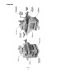
Features Figure 1 6
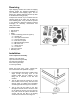
Receiving Open shipping container and check for shipping damage. Report any damage immediately to your distributor and shipping agent. Do not discard any shipping material until the Rip Saw is installed and running properly. Compare the contents of your container with the following parts list to make sure all parts are intact. Missing parts, if any, should be reported to your distributor. Read the instruction manual thoroughly for assembly, maintenance and safety instructions.
4. Place a level upon the machine table, and adjust the screws over the foot pads as necessary. When the machine is level, tighten all four hex nuts against the machine’s base. Unpainted surfaces, such as the work table and fence, have been given a protective coating at the factory. This should be removed with a soft rag moistened with a good commercial solvent. Do not use acetone, lacquer thinner, gasoline or any flammable solvents. Do not use an abrasive pad.
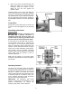
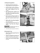
Installing/Changing Blade 1. Disconnect machine from power source. 2. Unscrew knurled knob on blade guard and swing guard away, as shown in Figure 8. 3. Loosen the arbor lock lever (A, Figure 7) and raise the arbor with the handwheel (B, Figure 7) until the blade can slip on to the arbor without interference from the caterpillar. 4. Place the arbor wrench on the flat of the arbor shaft. Place the T-wrench on the screw head as shown (Figure 8).
Adjustments Main Belt Tension 1. Disconnect machine from power source. 2. Open back panels to expose the motor, pulleys and belts, as shown in Figure 10. Loosen hex nut (Fig. 11) and turn the adjustment screw as needed to adjust the tension. Proper tension is achieved when there is a small amount of deflection by using moderate finger pressure on the belt midway between the pulleys. 3. Tighten hex nut (Fig. 11) and replace panels. Figure 10 Figure 11 Gearbox Belt Tension 1.
Feed Speed The feed speed adjuster is found below the gearbox (Figure 13). Feed speed should be adjusted while the machine is running and the caterpillar is in motion. Turn adjuster clockwise to decrease feed speed, counterclockwise to increase. Fence Alignment For accurate cutting, the fence must be parallel to the line of cut: Figure 13 1. Place a straight edge against the fence with its other side flush to the blade, and check that the fence is in line with the blade. 2.
Oiler Adjustment 1. Remove plastic cover. 2. Loosen set screw (Figure 17) and rotate knurled dial clockwise to increase oil output; counter-clockwise to decrease oil output. The scale is in cubic centimeters. 3. Retighten set screw, and install plastic cover. Operation 1. Check the oil tank at the infeed side of the machine (Figure 18). If it is not full, remove the cap and add light 20-weight oil through the fill hole. Replace cap when finished.
Oil should be checked weekly, and more added if necessary. Use light 20-weight oil. Change the oil after 2000 hours of operation. Insufficient oil may cause fast wear of gears; excessive oil into the gear reducer may cause oil leakage. Never overfill the oil tank, and never use recycled oil. Maintenance Before doing maintenance on the machine, disconnect it from the electrical supply by pulling out the plug or switching off the main switch! Failure to comply may cause serious injury.
Troubleshooting (Mechanical) Trouble Probable Cause Remedy Saw arbor won’t run. Saw arbor guard or rear guard not closed. Check and close guards. Caterpillar won’t move. Variable speed belt too loose, or dropped. Adjust variable speed belt tension or replace belt. See page 11. Workpiece slips. Pressure roller too high. Lower the pressure roller. Convex cut causes jointing failure. Saw blade too dull. Replace blade (page 10). Fence is bumped. Adjust fence (page 12).
Replacement Parts Replacement parts are listed on the following pages. To order parts or reach our service department, call 1-800-274-6848 Monday through Friday, 8:00 a.m. to 5:00 p.m. CST. Having the Model Number and Serial Number of your machine available when you call will allow us to serve you quickly and accurately. Non-proprietary parts, such as fasteners, can be found at local hardware stores, or may be ordered from Powermatic.
Parts List: Infeed Body Assembly Index No. Part No. Description Size Qty ................. SLR12-300 ............... Cover Assembly (Items 1 thru 7) ......................... .................................... 1 ................. SLR12-100 ............... Gear Box Assembly (Items 1 thru 10, 33, 36 and 43) .............................. 1 1 ............... TS-1502041 ............. Socket Head Cap Screw ...................................... M5x16 ......................... 4 2 ...............
Infeed Body Assembly 17
Parts List: Arbor Spindle Assembly Index No. Part No. Description Size Qty ................. SLR12-200 ............... Arbor Spindle Assembly (Items 1 thru 13) ........... .................................... 1 1 ............... TS-1492041 ............. Hex Cap Screw .................................................... M12x40 ....................... 1 2 ............... TS-2361121 ............. Lock Washer ........................................................ M12 ........................... 14 3 .....
Arbor Spindle Assembly 19
Parts List: Motor and Drive Unit Assembly Index No. Part No. Description Size Qty 1 ............... SLR12-501 ............... Eye-Bolt................................................................ .................................... 1 2 ............... TS-2311161 ............. Hex Nut ................................................................ M16 ............................. 2 3 ............... SLR12-502 ............... Adjustment Nut .................................................... M16 ..
Motor and Drive Unit Assembly 21
Parts List: Laser Assembly (Optional Accessory) Index No. Part No. Description Size Qty ................. SLR12-700 ............... Laser Assembly (Items 1 thru 18) ........................ ...................................... 1 ............... TS-1503081 ............. Socket Head Cap Screw ...................................... M6 x 35 ....................... 2 2 ............... SLR12-701 ............... Clamp Seat .......................................................... ...........................
Parts List: Roller and Frame Assembly Index No. Part No. Description Size Qty ................. SLR12-300 ............... Cover Assembly (Items 1 thru 7) ......................... .................................... 1 1 ............... SLR12-301 ............... Cover w/ Dust Port ............................................... .................................... 1 2 ............... SLR12-302 ............... Rotation Shaft ...................................................... .........................
60 ............. TS-1534042 ............. Pan Head Machine Screw ................................... M6x12 ......................... 2 61 ............. TS-1504051 ............. Socket Head Cap Screw ...................................... M8x25 ......................... 1 62 ............. SLR12-339 ............... Side Guard ........................................................... .................................... 1 63 ............. SLR12-340 ............... Arm.........................................
Roller and Frame Assembly 25
Parts List: Table and Stand Assembly Index No. Part No. Description Size Qty ............ SLR12-400FAN........ Fence Complete Assembly (Index 15, 20-24, 26-31, 52-58, 77, 81-84) .. 1 1 ............... SLR12-401 ............... Bracket ................................................................. .................................... 1 2 ............... TS-1506051 ............. Socket Head Cap Screw ...................................... M12x40 ....................... 4 3 ............... TS-2361121 ..
Index No. Part No. Description Size Qty 62 ............. SLR12-437 ............... Emergency Stop Button ....................................... .................................... 1 64 ............. SLR12-438 ............... Start Button .......................................................... .................................... 2 65 ............. SLR12-440 ............... Stop Button .......................................................... .................................... 2 67 .............
Table and Stand Assembly 28
Parts List: Electrical Control Panel (SLR12-443) Index No. Part No. Description Size Qty 1 ............... SLR12-601 ............... Control Relay ................... R1 .............................. MY2NJ-200/220VAC .. 1 2 ............... SLR12-602 ............... Timer ................................ T1 ............................... .................................... 1 3 ............... SLR12-603 ............... Transformer...................... PT .............................. 0V~440V ........
Electrical Connections – 3 Phase, 230V, 60Hz 30
Electrical Connections – 3 Phase, 460V, 60Hz 31
Preventive Maintenance Checklist for Model SLR12 Straight Line Rip Saw [ ] Work area around machine marked off clearly. [ ] Non-skid floor strips in area where operator normally stands. [ ] Inspect entire machine for loose bolts, nuts, screws. Tighten and replace as necessary. [ ] Clean table area, removing sawdust and chips with a soft bristle brush. Remove gum and pitch with oven cleaner. [ ] Lubricate appropriate places with a good grade non-hardening grease.
Warranty and Service Powermatic warrants every product it sells against manufacturers’ defects. If one of our tools needs service or repair, please contact Technical Service by calling 1-800-274-6846, 8AM to 5PM CST, Monday through Friday. Warranty Period The general warranty lasts for the time period specified in the literature included with your product or on the official Powermatic branded website. Powermatic products carry a limited warranty which varies in duration based upon the product.
This page intentionally left blank.
This page intentionally left blank.
427 New Sanford Road LaVergne, TN 37086 Phone: 800-274-6848 www.powermatic.