This .pdf document is bookmarked Operating Instructions and Parts Manual Wide Belt Sanders Models WB-25, WB-37, WB-43 model WB-37 shown Powermatic 427 New Sanford Rd. LaVergne, TN 37086 Ph.: 800-274-6848 www.powermatic.com Part No.
1.0 Warranty and Service Powermatic warrants every product it sells against manufacturers’ defects. If one of our tools needs service or repair, please contact Technical Service by calling 1-800-274-6846, 8AM to 5PM CST, Monday through Friday. Warranty Period The general warranty lasts for the time period specified in the literature included with your product or on the official Powermatic branded website. • Powermatic products carry a limited warranty which varies in duration based upon the product.
2.0 Table of Contents Section Page 1.0 Warranty and Service ....................................................................................................................... 2 2.0 Table of Contents ............................................................................................................................. 3 3.0 Safety warnings ................................................................................................................................ 5 4.0 Introduction...........
16.8.1 Pressure Bar Assembly – Models WB-25, WB-37, WB-43 ...................................................... 43 16.8.2 Parts List: Pressure Bar Assembly – Model WB-25 ................................................................. 43 16.8.3 Parts List: Pressure Bar Assembly – Model WB-37 ................................................................. 44 16.8.4 Parts List: Pressure Bar Assembly – Model WB-43 ................................................................. 44 16.9.
3.0 Safety warnings 1. Read and understand the entire owner’s manual before attempting assembly or operation. 2. Read and understand the warnings posted on the machine and in this manual. Failure to comply with all of these warnings may cause serious injury. 3. Replace the warning labels if they become obscured or removed. 4. This sander is designed and intended for use by properly trained and experienced personnel only.
3.0 Safety warnings 19. Make your workshop child proof with padlocks, master switches or by removing starter keys. 20. Give your work undivided attention. Looking around, carrying on a conversation and “horse-play” are careless acts that can result in serious injury. 21. Remove loose items and unnecessary work pieces from the area before starting the machine. 22. Maintain a balanced stance at all times so that you do not fall or lean against the conveyor belt or other moving parts.
4.0 Introduction This manual is provided by Powermatic covering the safe operation and maintenance procedures for a Powermatic WB Series Wide Belt Sander. This manual contains instructions on installation, safety precautions, general operating procedures, maintenance instructions and parts breakdown. This machine has been designed and constructed to provide years of trouble free operation if used in accordance with instructions set forth in this manual.
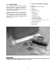
6.0 Unpacking 6.1 Contents of Shipping Container Open shipping container and check for shipping damage. Report any damage immediately to your distributor and shipping agent. Do not discard any shipping material until the sander is installed and running properly. 1 2 1 1 1 Compare the contents of your container with the following parts list to make sure all parts are intact. Missing parts, if any, should be reported to your distributor.
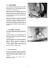
7.0 Assembly The sander should be placed on a level, sturdy floor, preferably concrete, with plenty of space surrounding it for on- and off-loading of stock, and general maintenance work. Open the two lower side panels and use the leveling screws inside the cabinet (Figure 1) to level the sander. The machine can also be secured to the floor with high quality lag screws (not provided) through the four mounting holes inside the cabinet.
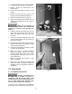
7.3 Installing/Replacing Sanding Belt 1. Machine should be disconnected from power source. 2. Turn the air valve switch (A, Figure 3) to Off position. 3. Remove the lock screw (B, Figure 3) by turning it counterclockwise and lifting up. 4. Remove the spacer block (C, Figure 3). 5. Inspect the sanding belt for defects such as chipped or torn edges. Do not use a belt if it is damaged. Make sure the direction of the arrows on the inside of the sanding belt matches the rotation of the machine. See Figure 4. 6.
electric current to reduce the risk of electric shock to the operator. Improper connection of the equipmentgrounding conductor can result in risk of electric shock. The conductor, with insulation having an outer surface that is green with or without yellow stripes, is the equipment-grounding conductor. If repair or replacement of the electric cord or plug is necessary, do not connect the equipmentgrounding conductor to a live terminal.
5. Press the Up S or Down T button on the keypad (see page 18 for detailed keypad instructions). Make sure the conveyor table moves in the same direction as indicated on the button. 6. If the conveyor table moves in the wrong direction, turn off the machine and disconnect from power. Switch any two of the three incoming power leads at R,S,T. 7. Re-connect power to the sander. 8.3 460 Volt Conversion To convert the sander to 460V: 1. Disconnect sander from power source. 2.
may result in incorrect tracking. If this occurs, the oscillation timing can be set to compensate. 1. Adjust oscillation while the machine is running. Turn on the air valve switch and press the sanding belt start button (see Figure 19). 2. The upper roller will pivot left and right. The duration of the sanding belt’s oscillation to the right side and to the left should be equal. For example, if the oscillation time to the right is one second, then the oscillation time to the left should also be one second.
9.4 Platen Position The sander has a removable platen with a graphite strip and a felt pad to reduce friction against the sanding belt. Positioning of the platen depends upon the type of wood being used. The height of the platen is set at the factory, but can be re-adjusted by rotating the platen adjustment knob (Figure 10). Each mark on the scale indicates a raising or lowering measurement of 0.005mm. One complete rotation of the scale moves the platen 0.2mm or approximately 8/1000 of an inch.
1. Disconnect sander from power source. 2. Loosen the lower hex nut (A, Figure 11/12) on the motor base. 3. Tighten the top hex nut (B, Figure 11/12) to lower the motor plate until proper tension is achieved. 4. When the belt is properly tensioned, you should be able to push in the belt approximately 3/4” at a point midway between the pulleys using moderate finger pressure. 5. Re-tighten the bottom hex nut (B, Figure 11/12) against the bottom of the motor plate.
1. Remove the four screws securing the emergency stop cover and remove the cover. See Figure 13. This will allow better inspection of the belt’s movement on the roller. 2. Turn on the conveyor belt. 3. Adjust tracking using the same adjustment screws that were used for tensioning in Figure 13. 4. If the conveyor belt is moving to the right side, turn the right screw clockwise. This will return the tracking toward the left. 5. If the conveyor belt is moving to the left side, turn the left screw clockwise.
If the ends of the workpiece are sniped, the front pressure bars are too low. The pressure should be enough to firmly hold the workpiece against the conveyor, but not so hard that the ends of the workpiece spring up after clearing the bar. Also, if the ends of the bars are not exerting equal pressure, the workpiece will tend to move sideways on the conveyor during sanding. To raise or lower each set of pressure bars: 1. Disconnect sander from power source. 2.
If the readings are different, the table needs adjusting. 2. Disconnect sander from power source. 3. At the area of the table that needs adjustment, loosen the two screws (A, Figure 18) on the bracket of the elevation screw, and rotate the bracket as needed. (The elevation screw is protected by the dust guard bellow.) Turn the elevating screw clockwise to lower the table in that area, counterclockwise to raise the table (see Figure 18).
10.2.1 Calibration To establish the distance between conveyor table and sanding belt, proceed as follows: 1. Connect power and air to the sander, and turn the air valve switch on to tighten the sanding belt. NOTE: The controller will not move the table if the air valve switch is off. 2. Press and hold the UP S button on the keypad to raise the conveyor table until the thicknesser knob (Figure 21) contacts the limit switch. The table will automatically stop while making slight contact with the sanding belt.
If the sanding belt breaks, all movement will be stopped, though the conveyor table can still be raised or lowered. The water should be removed daily from inside the filter cups. On the filter/regulator at the back of the cabinet, press the drain cock (see Figure 2). On the filter inside the cabinet, unscrew the cup to empty it. Once the machine has stopped, the operator should find where the braking system was tripped, and make the necessary adjustments. The machine can then be re-set and started.
14.0 Troubleshooting the Sander Trouble Probable Cause Remedy Sander will not start. No incoming power. Check that sander is connected to power, fuses are not blown or circuit breakers are not tripped. Low voltage. Check voltage at power source. Loose wiring. Inspect and remedy any loose connections on sander. Starting switch is defective. Replace switch. Motor is defective. Replace motor. Grit of sanding belt is too fine. Choose a larger grit of sanding paper.
Trouble Probable Cause Remedy The rear end of stock is thinner than the front. Front pressure bar is too low in relation to the contact drum. Raise front pressure bar (page 16). Uneven thickness between the left and right sides of the workpiece. Table not positioned correctly in relation to contact drum. Adjust table until it is parallel left to right (pages 17-18). Front pressure bar not in correct position in relation to contact drum. Adjust front pressure bar to parallel. See page 16.
15.0 Troubleshooting the LED Unit Trouble Probable Cause Remedy The display fails to show figures. Fuse is burned out. Replace 1A fuse. Control unit is malfunctioning. Unit must be repaired or replaced by authorized service personnel. Wrong figures were input. Input the proper numbers in accordance with the actual dimensions. Display shows abnormal figures. If the above step is ineffective, turn the power off and then on.
16.1.1 Base and Motor Assembly – Model WB-25 ONLY Parts list on page 25.
16.1.2 Parts List: Base and Motor Assembly – Model WB-25 Exploded view on page 24. Index No. Part No. Description Size Qty 1............... WB25-201................Machine Base........................................................................................ 1 2............... WB25-202................Motor Plate ............................................................................................ 1 3............... WB25-203................Rod ................................................
16.2.1 Base and Motor Assembly – Model WB-37 ONLY Parts list on page 27.
16.2.2 Parts List: Base and Motor Assembly – Model WB-37 Exploded view on page 26. Index No. Part No. Description Size Qty 1............... WB37-201................Machine Base........................................................................................ 1 2............... WB37-202................Motor Plate ............................................................................................ 1 3............... WB37-203................Rod ................................................
16.3.1 Base and Motor Assembly – Model WB-43 ONLY Parts list on page 29.
16.3.2 Parts List: Base and Motor Assembly – Model WB-43 Exploded view on page 28. Index No. Part No. Description Size Qty 1............... WB43-201................Machine Base........................................................................................ 1 2............... WB43-202................Motor Plate ............................................................................................ 1 3............... WB43-203................Rod ................................................
16.4.1 Upper Cabinet Assembly – Model WB-25 ONLY Parts list on page 31.
16.4.2 Parts List: Upper Cabinet Assembly – Model WB-25 Exploded view on page 30. Index No. Part No. Description Size Qty 1............... WB25-301................Upper Cabinet ....................................................................................... 1 2............... TS-1534032 .............Pan Head Screw ................................................M6x10 ........................ 7 3............... WB25-303................Upper Left Door ...............................................
16.5.1 Upper Cabinet Assembly – Models WB-37, WB-43 Parts list on page 33.
16.5.2 Parts List: Upper Cabinet Assembly – Model WB-37 Exploded view on page 32. Index No. Part No. Description Size Qty 1............... WB37-301................Upper Cabinet ....................................................................................... 1 2............... TS-1534032 .............Pan Head Screw ................................................M6x10 ........................ 8 3............... WB25-303................Upper Left Door ...............................................
16.6.1 Table Raising Assembly – Models WB-25, WB-37, WB-43 Parts list on page 35 (WB-25), page 36 (WB-37) and page 37 (WB-43).
16.6.2 Parts List: Table Raising Assembly – Model WB-25 Exploded view on page 34. Index No. Part No. Description Size Qty 1............... 6294297...................Elevation Screw..................................................................................... 4 2............... TS-0051051 .............Hex Cap Screw ..................................................5/16-18x1 ................... 8 3. .............. TS-0680031 .............Flat Washer .................................................
56 ............. 6294340...................Sprocket Wheel Adjustment Piece ......................................................... 1 57 ............. 6294341...................Sprocket Wheel Shaft ............................................................................ 1 58 ............. BB-6003ZZ ..............Bearing...............................................................6003ZZ....................... 1 59 ............. 6294343...................Adjustment Sprocket Wheel ......................
48 ............. WB25-448................Switch Plate .......................................................................................... 1 49 ............. TS-0050011 .............Hex Cap Screw ..................................................1/4-20x1/2 .................. 1 50 ............. WB25-450................Switch ................................................................................................... 1 51 ............. TS-2283302 .............Screw ...............................
40 ............. 6294333...................Motor Base Adjustment Rod .................................................................. 1 41 ............. TS-0680061 .............Flat Washer ........................................................1/2 .............................. 2 42 ............. WB25-149................Hex Nut ..............................................................1/2-12 ......................... 3 43 ............. TS-0720111 .............Lock Washer .............................
16.7.1 Table and Conveyor Belt Assembly – Models WB-25, WB-37, WB-43 Parts list on page 40 (WB-25), page 41 (WB-37) and page 42 (WB-43).
16.7.2 Parts List: Table and Conveyor Belt Assembly – Model WB-25 Exploded view on page 39. Index No. Part No. Description Size Qty 1............... WB25-501................Conveyor Table ..................................................................................... 1 2............... WB25-502................Conveyor Belt ........................................................................................ 1 3............... WB25-503................Mounting Bracket.............................
16.7.3 Parts List: Table and Conveyor Belt Assembly – Model WB-37 Exploded view on page 39. Index No. Part No. Description Size Qty 1............... WB37-501................Conveyor Table ..................................................................................... 1 2............... WB37-502................Conveyor Belt ........................................................................................ 1 3............... WB25-503................Mounting Bracket.............................
16.7.4 Parts List: Table and Conveyor Belt Assembly – Model WB-43 Exploded view on page 39. Index No. Part No. Description Size Qty 1............... WB43-501................Conveyor Table ..................................................................................... 1 2............... WB43-502................Conveyor Belt ........................................................................................ 1 3............... WB43-503................Mounting Bracket.............................
16.8.1 Pressure Bar Assembly – Models WB-25, WB-37, WB-43 Parts list on page 43 (WB-25) and page 44 (WB-37, WB-43). 16.8.2 Parts List: Pressure Bar Assembly – Model WB-25 Index No. Part No. Description Size Qty 1............... WB25-601................Roller Slider, Female ............................................................................. 2 2............... 6294391...................Roller Slider, Male ................................................................................. 2 3.....
16.8.3 Parts List: Pressure Bar Assembly – Model WB-37 Exploded view on page 43. Index No. Part No. Description Size Qty 1............... WB25-601................Roller Slider, Female ............................................................................. 2 2............... 6294391...................Roller Slider, Male ................................................................................. 2 3............... 6294392...................Front Roller Slider, Female ..........................
16.9.1 Platen Assembly – Model WB-25 only Parts list on page 45. 16.9.2 Parts List: Platen Assembly – Model WB-25 Index No. Part No. Description Size Qty 1............... WB25-701................Hex Cap Screw ..................................................1/2-12x1-1/2 ............... 4 2............... TS-0720111 .............Lock Washer ......................................................1/2 .............................. 4 3............... TS-0060061 .............Hex Cap Screw ......................
Index No. Part No. Description Size Qty 7............... TS-0207041 .............Socket Head Cap Screw.....................................1/4-20x3/4 .................. 2 8............... 6290294...................Screw Rod............................................................................................. 1 9............... 6290295...................Platen Lock Lever .................................................................................. 1 10 ............. 6290296...................
16.10.1 Platen Assembly – Models WB-37, WB-43 Parts list on page 47 (WB-37) and page 48 (WB-43). 16.10.2 Parts List: Platen Assembly – Model WB-37 Index No. Part No. Description Size Qty 1............... WB25-701................Hex Cap Screw ..................................................1/2-12x1-1/2 ............... 4 2............... TS-0720111 .............Lock Washer ......................................................1/2 .............................. 4 3............... TS-0060061 .............
Index No. Part No. Description Size Qty 8............... 6290294...................Screw Rod............................................................................................. 1 9............... 6290295...................Platen Lock Lever .................................................................................. 1 10 ............. 6290296...................Scale Ring Base .................................................................................... 1 11 ............. 6290297....
3............... TS-0060061 .............Hex Cap Screw ..................................................3/8-16x1-1/4 ............... 3 4............... TS-0720091 .............Lock Washer ......................................................3/8 .............................. 3 5............... 6290291...................Diaphragm............................................................................................. 1 6............... 6290292...................Adjustment Knob .........................
16.11.1 Air Regulator Assembly – Models WB-25, WB-37, WB-43 Parts list on page 50 (WB-25), page 51 (WB-37) and page 52 (WB-43). 16.11.2 Parts List: Air Regulator Assembly – Model WB-25 Index No. Part No. Description Size Qty ................. WB25-FCA ..............Filter Cup Assembly (index # 1,2,3,5,6,7)............................................... 1 1............... 6294544...................Filter Cup ..............................................................................................
Index No. Part No. Description Size Qty 29 ............. 6294571...................Flexible Hose......................................................ψ8×1400mm............... 1 30 ............. WB25-930................Flexible Hose......................................................ψ6×1100mm............... 1 31 ............. WB25-931................Flexible Hose......................................................ψ6×500mm................. 1 32 ............. WB25-932................Flexible Hose......
16.11.4 Parts List: Air Regulator Assembly – Model WB-43 Exploded view on page 50. Index No. Part No. Description Size Qty ................. WB25-FCA ..............Filter Cup Assembly (index # 1,2,3,5,6,7)............................................... 1 1............... 6294544...................Filter Cup .............................................................................................. 1 2............... 6294545...................Pressure Regulator.........................................
16.12.1 Sanding Belt and Accessories – Models WB-25, WB-37, WB-43 Parts list on page 54.
16.12.2 Parts List: Sanding Belt and Accessories – Model WB-25 Exploded view on page 53. Index No. Part No. Description Size Qty 1............... 6290281...................Platen Pull Hook .................................................................................... 1 2............... 6294461...................Limit Switch Tube .................................................................................. 2 3............... WB25-1003 ..............Tool Box ....................................
16.13.1 Tension Roller Assembly – Models WB-25 and WB-37 ONLY Parts list on page 56 (WB-25) and page 57 (WB-37).
16.13.2 Parts List: Tension Roller Assembly – Model WB-25 Exploded view on page 55. Index No. Part No. Description Size Qty 1. .............. TS-0720111 .............Lock Washer ......................................................1/2 .............................. 1 2. .............. TS-0208041 .............Socket Head Cap Screw.....................................5/16-18x3/4 ................ 6 3............... TS-1490031 .............Hex Cap Screw ..................................................
Index No. Part No. Description Size Qty 61 ............. TS-1533032 .............Pan Head Screw ................................................M5x10 ........................ 6 62 ............. WB25-162................Seal....................................................................................................... 1 63 ............. WB25-ACA ..............Air Cylinder Assembly............................................................................ 1 16.13.
Index No. Part No. Description Size Qty 49 ............. WB25-149................Hex Nut ..............................................................1/2-12 ......................... 1 56 ............. TS-0720051 .............Lock Washer ......................................................#10 ............................. 6 57 ............. TS-0051011 .............Hex Cap Screw ..................................................5/16-18x1/2 ................ 3 59 ............. WB25-159................
16.14.1 Tension Roller Assembly – Model WB-43 ONLY Parts list on page 60.
16.14.2 Parts List: Tension Roller Assembly – Model WB-43 Exploded view on page 59. Index No. Part No. Description Size Qty 1............... WB25-162................Seal....................................................................................................... 1 2. .............. TS-0720111 .............Lock Washer ......................................................1/2 .............................. 7 3............... TS-0208041 .............Socket Head Cap Screw..........................
Index No. Part No. Description Size Qty 63 ............. WB43-163................Frame Support ...................................................................................... 1 64 ............. TS-1533032 .............Pan Head Screw ................................................M5x10 ........................ 6 65 ............. TS-0051011 .............Hex Cap Screw ..................................................5/16-18x1/2 ................ 4 66 ............. WB43-ACA ..............
16.15.1 Electrical Box Assembly – Models WB-25 and WB-37 Parts list on page 63 (WB-25) and 64 (WB-37).
16.15.2 Parts List: Electrical Box Assembly – Model WB-25 Exploded view on page 62. Index No. Part No. Description Size Qty 1............... WB25-801................Electrical Control Box ........................................................................... 1 2............... 6294516...................Hinge Pin .............................................................................................. 2 3............... WB25-803................Electrical Control Box Door .......................
16.15.3 Parts List: Electrical Box Assembly – Model WB-37 Exploded view on page 62. Index No. Part No. Description Size Qty 1............... WB25-801................Electrical Control Box ........................................................................... 1 2............... 6294516...................Hinge Pin .............................................................................................. 2 3............... WB25-803................Electrical Control Box Door .......................
16.16.1 Electrical Box Assembly – Model WB-43 ONLY Parts list on page 66.
16.16.2 Parts List: Electrical Box Assembly – Model WB-43 Exploded view on page 65. Index No. Part No. Description Size Qty 1............... WB43-801................Electrical Control Box ........................................................................... 1 2............... 6294516...................Hinge Pin .............................................................................................. 2 3............... WB43-803................Electrical Control Box Door .......................
17.0 Electrical Connections 17.
17.