Operating Instructions and Parts Manual 25-inch Planer Model WP2510 WMH TOOL GROUP 2420 Vantage Drive Elgin, Illinois 60124 Ph.: 800-274-6848 www.wmhtoolgroup.com Part No.
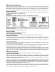
Warranty and Service WMH Tool Group, Inc., warrants every product it sells. If one of our tools needs service or repair, one of our Authorized Service Center located throughout the United States can give you quick service. In most cases, any of these WMH Tool Group Authorized Service Centers can authorize warranty repair, assist you in obtaining parts, or perform routine maintenance and major repair on your POWERMATIC® tools. For the name of an Authorized Service Center in your area call 1-800-274-6848.
Table of Contents Warranty and Service .............................................................................................................................. 2 Table of Contents .................................................................................................................................... 3 Warning................................................................................................................................................... 5 Introduction .....................
Parts List: Electrical Box Assembly..................................................................................................... 53 Electrical Connections – 230Volt............................................................................................................ 54 Electrical Connections – 460Volt............................................................................................................
Warning 1. Read and understand the entire owners manual before attempting assembly or operation. 2. Read and understand the warnings posted on the machine and in this manual. Failure to comply with all of these warnings may cause serious injury. 3. Replace the warning labels if they become obscured or removed. 4. This planer is designed and intended for use by properly trained and experienced personnel only.
blahblahblah 19. Make your workshop child proof with padlocks, master switches or by removing starter keys. 20. Give your work undivided attention. Looking around, carrying on a conversation and “horse-play” are careless acts that can result in serious injury. 21. Maintain a balanced stance at all times so that you do not fall or lean against moving parts. Do not overreach or use excessive force to perform any machine operation.
Introduction This manual is provided by WMH Tool Group covering the safe operation and maintenance procedures for a Powermatic Model WP2510 Planer. This manual contains instructions on installation, safety precautions, general operating procedures, maintenance instructions and parts breakdown. This machine has been designed and constructed to provide years of trouble free operation if used in accordance with instructions set forth in this manual.
1 1 5 1 1 1 1 20 Air Impact Screwdriver – (C) RA-30E 460V Overload Relay – (D) Star Point Screwdrivers – (E) Breaker Bar – (F) Air Valve – (G) Air Valve Mounting Bracket – (H) Air Valve Pressure Gauge – (J) Flat Head Spline Socket Screws, M6x14 – (K) 10 Spline Bits, T-20 – (L) 10 Replacement Knife Inserts – (M) 1 Handle with Knob – (N) 3 Open End Wrenches, 17-19, 22-24, and 1214 mm – (O) 1 Reversible Screwdriver – (P) 4 Hex Wrenches, 3, 4, 5, and 8mm – (R) 8 Button Head Socket Screws, M6x12 – (S) 8 Lock Wa
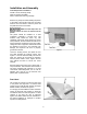
Installation and Assembly Tools Required for Installation: Forklift or hoist, with lifting straps 4mm hex wrench (provided) 22mm combination wrench (provided) Remove any straps or boards holding the planer to the pallet. Place straps under the four lifting hooks at front and back to raise the planer off the pallet and move it to location. Make sure the straps will not damage buttons or levers on the front of the planer. The planer should be installed on a solid foundation, preferably a concrete floor.
Grounding Instructions Electrical connections must be made by a qualified electrician in compliance with all relevant codes. This machine must be properly grounded to help prevent electrical shock and possible fatal injury. This machine must be grounded. In the event of a malfunction or breakdown, grounding provides a path of least resistance for electric current to reduce the risk of electric shock. Improper connection of the equipmentgrounding conductor can result in a risk of electric shock.
Converting from 230 Volt to 460 Volt Consult the diagrams on pages 54 and 55 for specific information on the following changes. 1. Disconnect machine from power source. 2. Change the lead connections to the main motor and to the table hoist motor. 3. Replace the RA-30 (230V) overload relay with the provided RA-30E (460V) overload relay. 4. Switch the “R” wire on the transformer from the 230V to the 460V terminal. 5. If using a plug, install a proper UL/CSA listed plug suitable for 460V operation.
Feed Rate The planer is equipped with selectable feed rate rollers that feed stock at 20, 25 or 30 feet per minute. To adjust speed, rotate the lever shown in Figure 4. IMPORTANT: Change feed rate only while the machine is running. Belt Tension 1. Disconnect machine from power source. 2. Remove the lower rear panel and use the four hex nuts on the motor mount to adjust belt tension. See Figure 5. Adjust motor plate up or down until correct belt tension is achieved.
2. Remove the top left side panel so that you can rotate the cutterhead using the belts. 3. To remove a knife insert, unscrew the flat head screw with a spline screwdriver, or the air-operated screwdriver using one of the provided T-20 spline bits. If the screw will not budge, place the hole of the breaker rod (A, Figure 7) over a spline bit (B, Figure 7) and lightly tap the breaker rod counterclockwise with a hammer to break loose the screw. 4. Remove the flat head screw, and remove the knife insert.
To provide proper drive, the infeed roller should be set so that the bottom of its arc is 1/16” below the arc of the cutterhead knife inserts. The infeed roller is under spring tension and this tension must be sufficient to feed the stock uniformly through the planer without slipping but should not be so tight that it causes damage to the boards. The tension should be equal at both ends of the roller. To adjust the infeed roller: 1. Disconnect machine from power source. 2.
A chipbreaker set too low or with excessive tension may prevent stock from feeding into the machine. Pressure Bar Most planing problems can be traced to improper setting of the pressure bar. Its function is to hold down the material after it passes under the cutterhead and throughout the remainder of the cut. Its basic setting is to be in line with the arc of the cutterhead knives. If it is too high, a shallow “clip” will occur at each end of the board. If it is too low, stock will not feed through.
The table rollers are adjusted at the factory. If they should need further or “fine” adjustment: 1. Disconnect machine from power source. 2. Loosen lock handle and position the quickset lever (Figure 12) to zero. 3. Use a dial gauge (not provided) to find the distance from table top to the apex of the table roller. Zero the gauge at this position. 4. Place the gauge over the extreme right side of the table roller and find the high point of the table roller arc. The gauge should still read zero. 5.
3. Loosen the three socket head cap screws (A, Figure 15) beneath the table. 4. Place a rod-like object (such as a hex wrench) into one of the open holes (B, Figure 15) and turn the shaft (C, Figure 15) to raise the table until the gauge reads the proper measurement. Or, the same effect can be achieved by lowering the other side of the table. 5. Re-tighten the socket head cap screws (A, Figure 15). Figure 15 Test Cutting and Troubleshooting Using a piece of semi-finished stock, set up for a 1/16” (1.
Feed restriction can also occur due to pitch buildup on the table. Be sure the table surface is clean. Dusting the surface with talc occasionally will aid in smoother feeding and help prevent pitch buildup. Clip Marks If clip marks occur 6” (152mm) in from each end of the board, the pressure bar is too high. See Figure 16. Turn both right and left hand adjusting screws (see Figure 11) the same amount, 1/4 turn clockwise or less, and take another 1/16” (1.59mm) deep cut. Re-examine the board.
Twisting If material twists while feeding through the planer, either the table rollers, pressure bar, or outfeed roller may be out of level. Refer to adjustment settings on pages 14 and 15. Halted Feeding If the infeed roller takes the stock, the chipbreaker lifts, and just as you hear the knives contact the material, the workpiece stops feeding; then the pressure bar is too low. Re-set the pressure bar (see page 15).
The recommended lubrication for roller chains used in medium to slow speed operation is to simply wipe the chain clean. When there is an appreciable buildup of dust, dirt or wood shavings, use an oil cloth but never pour the oil directly on the chain. Over-oiling defeats the purpose of the lubrication, since it tends to invite the collection of dust, shavings, etc. and works into members of the chain. This hastens wear and leads to premature replacement.
2. Operation Modes There are two base operating modes – MANUAL and SINGLE. In MANUAL mode, the operator can raise or lower the table using the Controller keypad. In SINGLE mode, the table will move to the pre-set value when you push the “Table Up” or “Table Down” buttons on the planer’s control panel. Press to select Manual mode or Single mode: When LED lamp is on – Manual mode. When LED lamp is off – Single mode.
SINGLE MODE In single mode, the device performs automatic positioning of the table to the programmed target position. The “Table Up” or “Table Down” button on the planer should be pushed and held; when the table has fully adjusted to the target position, the table will automatically stop in position. Release the push button. Setting Target Value Step 1: Press (Target window LED starts blinking) Step 2: Enter the target value using numerical keypad. Step 3: Press to complete.
Example: Assume: target value on display = 100.00mm real value on display = 100.00mm To change the target value to 20.25mm, Step 1: Press , the LED lamp on Target window is blinking. Display Step 2: Enter new target value (example: 20.25mm) Press Display Step 3: Press The Press to complete. LED lamp is blinking – ready for positioning. to start the positioning or press 23 to cancel.
3. Fast Program (10 sets) To facilitate frequently used positions, such as different board thicknesses, the keys 0 to 9 have associated preset target values. By pressing one of these keys, its target value is loaded automatically, and the positioning can be started immediately. Entering preset target values: Step 1: Press Step 2: Select a key 0 to 9 (total of 10 values). Step 3: Enter the target value. Step 4: Press to confirm. Follow the same procedure for entering the other preset target values.
Step 5: Press ...............................................[select program key 1] Step 6: Press ............................................[enter value] Step 7: Press ..................................................................[complete] Step 8: Press to exit. Execute: LED lamp is off. Step 1: Enter single mode, Step 2: Press a key 0 to 9. LED lamp is blinking, ready for start. Example: Program 0 = 10.00mm; Program 1 = 20.00mm. Step 1: In Single Mode, Step 2: Press LED lamp is off.
4. Select Counting direction You can select the counting direction according to the table movement. Step 1: Press Display Step 2: Press .......................[default] to change the direction. “-dir” numbers decrease as table rises (accords with scale on planer). “dir-“ numbers increase as table rises. Step 3: Press to confirm or press to clear. 5. Select Positioning Mode Step 1: Press Step 2: Press a. ---| |--b. ---| c. |--Step 3: Press to select.
6. Set Software Limit (Hi/Lo End) There are High and Low software limits. If these are exceeded, the display will give an error message. To set the Lo_End press To set the Hi_End press 7. Set Tolerances The tolerance defines the accuracy of the positioning. Step 1: Press Display .........................[default] Step 2: Enter the value for tolerance. Step 3: Press to confirm or press 27 to clear.
8. Set Low Speed Limit This function defines the speed level which is considered abnormal for the machine. When the Controller starts the table movement up or down, and the table does not move, or moves with a speed lower than defined, it stops the machine and displays: to clear. Press To set low speed limit: Step 1: Press Display ..........................
9. Set Linear Correction NOTE: Setting Linear Correction should be done in MM (metric) mode, not inches. This will ensure accurate readings for table movement. Step 1: Press Display Step 2: Enter the value between 0.0001 and 9.9999 Step 3: Press to confirm or press to clear. 10. Enter Parameter Setttings Mode With this function, you can select each parameter to be locked or unlocked. When a parameter is locked, then the end-user can only see the value, but can not change it.
11. Check Software Version To check the released version of the M15S Controller program: Step 1: Press Display In the real value window, you will see the released version. Step 2: Press to confirm or press to clear. 12. Load Datum Values The real value refers to the distance between the machine table and the cutterhead. Thus, the cutterhead defines the zero point of the machine. It is, however, difficult or impossible to move the planer table to this point.
Load the real value: Step 1: Press Display Step 2: Press to confirm or press to cancel. Example: The current value is 10.00mm but the actual thickness is 10.50mm.
13. IN/MM Conversion The dedicated mm/inch key allows for immediate switch of the units between millimeters and inches. The LEDs on the key indicate the selected unit. Switching between MM and INCHES has no effect on the control functions. 14. Set Device Resolution Step 1: Press Step 2: Use Step 3: Press to select resolution. to confirm or press 32 to clear.
15. Calibration Step 1: Press Display Step 2: Use to move the planer table until M15S terminates the calibration and restarts. 16. M15S Troubleshooting Display “Change RST” message appears when the Controller detects a motion in the wrong direction. For example, the Controller switches the outputs to move upward but the table starts moving in the reverse direction. Usually this is caused by the wrong wiring of the three phase motor. Press to clear. Check the wiring and change if necessary.
Display Possible cause: a. no sensor b. 9-pin connector is loose c. wire broken d. the gap between sensor and tape is too large Excluding: Check the sensor, sensor cable and sensor connector. Display Possible cause: Incorrect operation. Excluding: Press to clear. Display This message appears after power-on and indicates battery discharged. The C-type battery MUST be replaced to resume the operation of the device. Change as follows: 1.
17.
Troubleshooting: Planer Operating Problems Trouble Snipe. Fuzzy grain. Torn grain. Rough/raised grain. Rounded, glossy surface. Poor feeding of lumber. Probable Cause Remedy Table rollers not set properly. Adjust table rollers to proper height. Inadequate support of long boards. Support long boards with a roller stand. Uneven feed roller pressure front to back. Adjust feed roller tension. Dull knife inserts. Rotate or replace knife inserts. Lumber not butted properly.
Troubleshooting: Mechanical and Electrical Problems Trouble Probable Cause Remedy Uneven depth of cut side to side. Knife inserts not set correctly. Make sure knife inserts are set correctly and securely in cutterhead. Planer table not level with cutterhead. Level the table. See pages 16-17. Depth of cut scale is incorrect. Adjust depth of cut scale. Use LED control panel for greater precision. Inadequate chain tension. Adjust chain tension. Sprockets misaligned. Align sprockets.
Trouble Probable Cause Remedy Motor starter failure. Examine motor starter for burned or failed components. If damage is found, replace motor starter. If motor starter looks okay but is still suspect, you have two options: have a qualified electrician test the motor starter for function, or purchase a new starter and establish if that was the problem on changeout. Machine will not start/restart or repeatedly trips circuit breaker or blows fuses.
Column Assembly 39
Parts List: Column Assembly Index No. Part No. Description Size Qty 1............... WP2510-401............Idler Support Base................................................................................. 1 2............... TS-1540071 .............Hex Nut ..............................................................M10............................ 2 3............... TS-1550061 .............Flat Washer........................................................M8.............................. 1 4..........
58............. WP2510-458............Spring.................................................................................................... 1 59............. WP2510-459............Plate...................................................................................................... 1 60............. WP2510-460............Bolt........................................................................................................ 1 61............. TS-1505041 .............Socket Head Cap Screw.......
Gearbox Assembly 42
Parts List: Gearbox Assembly Index No. Part No. Description Size Qty ................. WP2510-100............Gearbox Assembly (index nos. 1 through 40)......................................... 1 1............... TS-1505021 .............Socket Head Cap Screw.....................................M10x20 ...................... 5 2............... 6012047...................Washer.................................................................................................. 1 3............... 6012046........
Parts List: Cutterhead Assembly Index No. Part No. Description Size Qty 1............... WP2510-201............Socket Head Cap Screw.....................................M10x75 ...................... 2 2............... TS-1550071 .............Flat Washer........................................................M10.......................... 12 3............... 6012132...................Spring.................................................................................................... 2 4.............
58............. 6012162...................Spring.................................................................................................... 6 59............. WP2510-259............Right Bracket......................................................................................... 1 60............. WP2510-260............Key.....................................................................8x7x16 ....................... 1 61............. 6012175...................Spring...........................
Table Assembly 46
Parts List: Table Assembly Index No. Part No. Description Size Qty 1............... WP2510-501............Roller Bracket........................................................................................ 4 2............... BB-6203VV..............Ball Bearing........................................................6203VV ...................... 4 3............... WP2510-503............Roller .................................................................................................... 2 4.......
Base Assembly 48
Parts List: Base Assembly Index No. Part No. Description Size Qty 1............... TS-1504031 .............Socket Head Cap Screw.....................................M8x16 ........................ 1 2............... TS-1550061 .............Flat Washer........................................................M8.............................. 1 3............... WP2510-603............Motor Pulley .......................................................................................... 1 4...............
60............. WP2510-660............S-Ring................................................................................................... 2 61............. WP2510-661............Sprocket................................................................................................ 1 62............. WP2510-662............S-Ring................................................................................................... 1 63............. BB-6203VV..............Ball Bearing........................
122........... VB-A86 ....................V-Belt .................................................................A86 ............................ 3 123........... VB-A57 ....................V-Belt .................................................................A57 ............................ 1 ................. WP2510-PCA ..........Power Cord Assembly (#124 - #128) ..................................................... 1 124........... WP2510-6124..........Red Cord.........................................
Parts List: Top Cover Assembly Index No. Part No. Description Size Qty 1............... TS-1504061 .............Socket Head Cap Screw.....................................M8x30 ........................ 4 2............... WP2510-302............Hinge .................................................................................................... 4 3............... TS-1505111 .............Socket Head Cap Screw.....................................M10x70 ...................... 2 4...............
Parts List: Electrical Box Assembly Index No. Part No. Description Size Qty 1............... TS-1531012 .............Screw.................................................................M3x6 .......................... 2 2............... WP2510-702............Electrical Box......................................................................................... 1 3............... WP2510-703............Power Supply ........................................................................................
Electrical Connections – 230Volt 54
Electrical Connections – 460Volt 55
WMH Tool Group 2420 Vantage Drive Elgin, Illinois 60124 Phone: 800-274-6848 www.wmhtoolgroup.